


Disassembly order
For convenience, disassembly procedures should be followed in a particular order. Use the following
table to determine the sequence in which to access major workstation components.
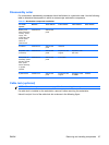
Table 5-3 Workstation component installation
To install/
replace...
Remove... Then remove... Then remove... Then remove... Then remove...
Battery, front
bezel, hard drive,
memory, power
supply, rear
system fan, side
access panel
sensor, or
solenoid lock
Chassis lock Side access
panel
Processor Chassis lock Side access
panel
Heatsink
Expansion card
(PCI/PCIe)
Chassis lock Side access
panel
Expansion card
support
Expansion card
slot cover
Front panel I/O
assembly, optical
bay filler, optical
drive, power
button assembly,
or system
speaker
Chassis lock Side access
panel
Front bezel
System board Chassis lock Side access
panel
Expansion card
support
Expansion cards
or DIMMs
Heatsink
Cable lock (optional)
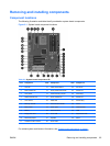
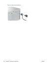
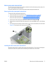
NOTE: Read Warnings and cautions on page 59 before servicing this component.
If a cable lock is installed on the workstation, remove it before servicing the workstation.
Unlock it and pull it out of the cable lock slot as shown in the following figure.
ENWW Removing and installing components 67