


Add-On Memory
149
Add-On Memory
Follow these procedures to add memory to an rp7400 server.
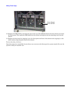
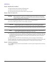
Memory Configuration Rules
rp7400 systems support up to 4 memory carriers (numbered 0, 1, 2, and 3), each with slots for 4 memory
DIMM pairs (numbered 0a/b, 1a/b, 2a/b, and 3a/b). For the DIMMs to work, both DIMMs in a slot pair must
be the same type (i.e., the same part number).
• Performance considerations. For best performance, install DIMMs evenly among the carriers, loading
carriers 0, 1, 2, and 3 in sequence. For example, four 512MB memory DIMM pairs should be loaded into
slot 0a/b on carrier 0, then slot 0a/b on carrier 1, and so on.
Although not a requirement for performance, the largest memory sizes should be installed first, making it
more convenient if the memory DIMMs are re-sequenced at a later time.
• Cooling considerations. The following will help optimize air flow cooling within the system.
Always install memory carriers in the sequence 0, 1, 2, than 3. For example, if you have only two memory
carriers, make sure they are installed as carrier 0 and carrier 1.
Install DIMMs into the carriers in the following slot order: 0a/b, 1a/b, 2a/b, 3a/b.
NOTE The most important rule is that DIMMs of the same type are distributed evenly amongst the
carriers. If necessary, remove and re-sequence existing memory modules to balance
the distribution; otherwise, a PDC error may occur.
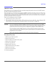
Procedure Overview
1. Remove power from the system.
2. Remove the front bezel.
3. Extend the SPU out the back of the cabinet.
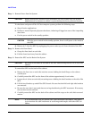
4. Remove the back top cover
5. Remove the back air baffle
6. Remove the memory carrier.
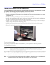
7. Install new memory DIMMs in the memory carrier.
8. Reinstall the memory carrier.
9. Replace the back air baffle
10. Replace the top cover.
11. Slide the SPU back into the cabinet.
12. Replace the front bezel.
13. Power ON the SPU.
14. Verify the installation.