


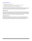


Specify Raised Floor Requirements
39
Specify Raised Floor Requirements
If a raised floor system is used, a complete grounding grid for maintaining equal potential over a broad band
of frequencies should be installed. The grounding grid should be connected to the equipment cabinet and
electrical service entrance ground at multiple connection points via minimum #6 AWG (16mm2) wire ground
connector.
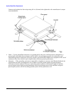
There are three types of raised floor systems:
• Free standing - consists solely of the tiles and pedestals supporting the tiles. Metal backing on the tiles
supports the weight from one pedestal to the next, and provides electrical continuity from one pedestal to
the next.
• Drop-in stringers - a simple metal bar extends from one pedestal to another, providing additional support
for the tile. Weight distribution and electrical continuity are improved over the free standing system.
• Bolt-in stringer - a metal bar extends from one pedestal to the next, but the bar is bolted into place,
providing additional electrical and mechanical security. The system provides the best electrical continuity
and weight distribution.
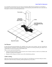
Bolt-in String System grounding: One approach to grounding for bolt-in stringer systems go around the entire
perimeter of the room, connecting every third pedestal with #4 AWG or #6 AWG wire. Then make an ‘X’
through the center part of the room with the wire. If the room is very large or irregularly shaped, several ‘X’s
may be required, all connected to the same perimeter ground.
Drop-in Stringer system grounding. Use the ‘X’ system described for drop-in stringer systems.
Free-standing system grounding:
• Excellent — Add a grounding strip to the subfloor. The grounding grid should be made of aluminum strips
mounted to the subfloor. The strips should be 0.032 in. (0.08 cm) thick and a minimum of 3.0 in. (8.0 cm)
wide.