


Add I/O Cards
157
The SPU should now be fully extended out the back of the cabinet.
WARNING Only extend one SPU at a time. Never attempt to extend more that one SPU
for any reason.
Step 4. Remove the PCI Cover Plate
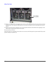
NOTE Steps 4 through 8 apply to the six PCI card slots on either side of the SPU. As viewed
from the rear of the cabinet, slots 1 through 6 are on the left side. The lowermost slot
in the array is slot 1. Slots 7 through 12 are on the right side, with slot 7 being the
lowermost slot in the array.
a. Loosen the two captive screws at the end of the I/O card slot cover.
b. Swing the cover away and off of the SPU.
Step 5. Insert the I/O Card Into the Slot
NOTE The PCI card slots have separators which protect against touching adjacent cards
when plugging in PCI cards. The separators also have tabs which facilitate removing
the cards.
a. Remove the metal slot cover, if present, at the rear of the SPU.
b. Align the PCI card with the appropriate slot.
c. Insert the PCI card into the card cage, between the separator/extractor cards.
d. Press firmly on the PCI card to be sure it is fully seated.
Step 6. Replace the PCI Cover Plate
a. Swing the I/O slot cover closed.
b. Tighten the two captive screws at the end of the slot cover.
NOTE The PCI card slots have separators which protect against touching adjacent cards
when plugging in PCI cards. The separators also have tabs which facilitate removing
the cards.
Step 7. Insert the SPU Back Into the Cabinet
CAUTION Be aware of the cables at the back of the SPU while moving the SPU in or out of the
cabinet.
To insert the SPU into the cabinet from the back:
a. Carefully insert the SPU all the way into the cabinet until the front of the SPU sticks out the
front approximately 2 to 4 inches.