


Add-On Memory
151
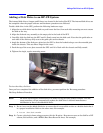
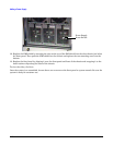
NOTE It is recommended that you pull the SPU from the back of the cabinet. This allows
you to monitor the cable movement to avoid snags and tangles with other SPUs or
cables.
The SPU should now be fully extended out the back of the cabinet.
WARNING Only extend one SPU at a time. Never attempt to extend more that one SPU
for any reason.
Step 4. Remove the Back Top Cover
CAUTION Operating the system without the back top cover in place can make the SPU
susceptible to EMI problems. Replace the back top cover before operating the system.
To remove a back top cover from the SPU:
a. Loosen the two captive screws along the back edge of the top cover.
b. Lift the back edge of the top cover up and away from the SPU
Step 5. Remove the Back Air Baffle
CAUTION Operating the system without the back air baffle will create air flow problems and
possibly shorten the life of the internal components. Hewlett-Packard does not
recommend the system be powered on with the air baffles removed. Also, operation of
the system without the top cover and air baffle in place can make the system
susceptible to EMI problems.
To remove the back air baffle from the:
a. Loosen the two captive mounting screws at the support bridge.
b. Grasp the air baffle along the extruded handle on the back edge of the air baffle and lift it out of
the SPU.
Step 6. Remove the Memory Carrier
The memory carriers (up to four) are located along the back of the SPU.
CAUTION Be sure to have an anti-static pad or ESD compliant work place to rest the memory
carrier on.
To remove the memory carrier from the SPU:
a. Grasp the insertion/extractor levers on the appropriate memory carrier and pull them up to
disengage the memory carrier form the system board.
b. Carefully pull the memory carrier out of the SPU.
Step 7. Install the Memory DIMMs in the Memory Carrier