


Introduction
Modbus/TCP Interface
2 HC900 Hybrid Controller Communications User Guide Revision 4
9/03
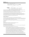
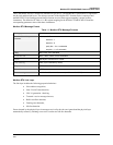
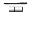
Figure 1-1 Modbus RTU Protocol within a TCP/IP Frame
The Open Modbus/TCP Specification is followed with respect to the physical, data link, and network layers. The
message structure within the Modbus frame uses standard Modbus RTU function codes.
The Address part of the Modbus frame is not used (set to 00) since there is no sub-addressing intended or required.
The controller IP address is the identifying address, set independently at the controller.
The error checking is supported by TCP/IP network protocols and not part of the Modbus frame.
The Transaction Identifiers and Protocol Identifiers in the header are normally all 0’s (4 bytes total) while the
Length field identifies the number of bytes in the Modbus frame. The controller will transmit the correct number of
bytes for the remainder of the frame. However, the controller does not check this field for messages received.
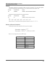
The standard IEEE 32-bit floating point and 16-bit integer formats are used.
Parameter Addressing
The definition in Table 6-1 is the register map overview listing starting and ending addresses.
Greater detail for parameter addressing relating to a particular function class, e.g, loops, setpoint programmer, signal
tags, etc. is in referenced sub-sections. Function Codes 1, 2, 3, 4, 5, 6, 8, 16 (10h), and 17 (11h) are supported (see
Table 4-1 Modbus/TCP and Modbus RTU Function Codes Definitions).
Examples for read or write access to parameters supported by the various function codes are provided in Sections
4.2 through 4.10.
Reference
The Open Modbus/TCP Specification can be obtained at the Modicon website:
http://www.modicon.com/openmbus/standards/openmbus.htm
HC900 Ethernet Communications Setup
See the HC900 Hybrid Control (HC) Designer Users Guide, Doc. # 51-52-25-110 or respective HC Designer Help
Files for setting up the following network parameters:
IP Address, Subnet Mask (optional), Default Gateway IP Address (optional)
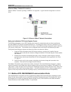
1. Be sure the PC, HMI panel, or other Host device has a Network Interface Card (NIC) with an IP
address (fixed or DHCP served) that allows access to controllers on the same or other subnet. Consult
your IT department or network administrator for allocating IP addresses to the controllers as required.
2. You will need to set each controller’s IP address prior to network connection since every HC900
controller is shipped with the default IP address of 192.168.1.254. Placing multiple controllers on the
same network before they have been given unique IP addresses will cause problems.
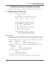
3. On the PC, use the Utilities Worksheet in the HC Designer software to set up the serial RS-232
connection to the controller at the desired baud rate. This will require a null modem cable.
4. Select the Set Controller’s Network Parameters button. Using the wizard (bottom radio button), select
the PC COM port to be used, then set the controller’s new network parameters including IP address,