


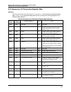

Register Map for Process and Operation Type Variables
Segment Register Map
Revision 4 HC900 Hybrid Controller Communications User Guide 69
9/03
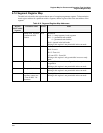
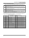
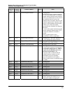
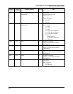
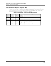
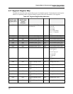
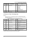
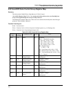
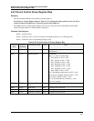
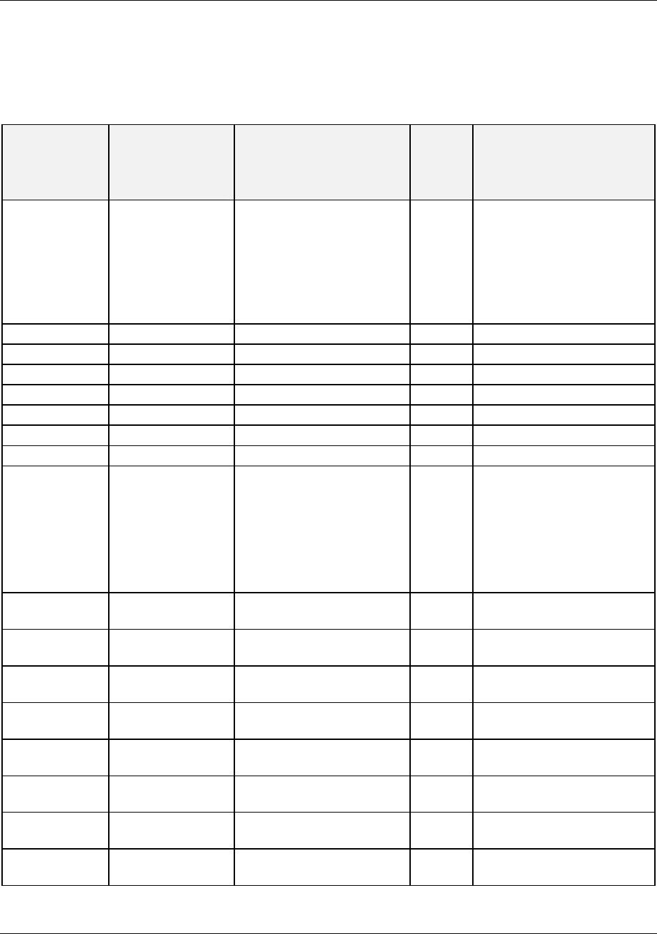
6.17 Segment Register Map
The table below describes the registers that are part of a schedule segment. To determine the actual register
address for a parameter within a segment, add the register offset to the start address of the segment.
Table 6-22 Segment Register Map Addresses
Register
Offset within
segment (Hex)
Register
Offset within
segment
(Decimal)
Parameter Name Access Notes
0000 0000 Guaranteed Soak Type 1
(Bit Packed)
R/W Bit Packed
Bit 0: Off
Bit 1: Low
Bit 2: High
Bit 3: Low & High
Bit 4…15: Unused
Note 1
0001 0001 Guaranteed Soak Type 2 R/W See Guaranteed Soak Type 1
0002 0002 Guaranteed Soak Type 3 R/W See Guaranteed Soak Type 1
0003 0003 Guaranteed Soak Type 4 R/W See Guaranteed Soak Type 1
0004 0004 Guaranteed Soak Type 5 R/W See Guaranteed Soak Type 1
0005 0005 Guaranteed Soak Type 6 R/W See Guaranteed Soak Type 1
0006 0006 Guaranteed Soak Type 7 R/W See Guaranteed Soak Type 1
0007 0007 Guaranteed Soak Type 8 R/W See Guaranteed Soak Type 1
0008 0008 Events R/W Bit Packed
Bit 0: Event #1
: :
Bit 15: Event #15
0: Event OFF
1: Event ON
Note 2
000A 0010 Time R/W Floating Point in seconds
Note 1
000C 0012 Output #1 Ramp or Soak
value
R/W Floating Point Note 1
000E 0014 Output #2 Ramp or Soak
value
R/W Floating Point Note 1
0010 0016 Output #3 Ramp or Soak
value
R/W Floating Point Note 1
0012 0018 Output #4 Ramp or Soak
value
R/W Floating Point Note 1
0014 0020 Output #5 Ramp or Soak
value
R/W Floating Point Note 1
0016 0022 Output #6 Ramp or Soak
value
R/W Floating Point Note 1
0018 0024 Output #7 Ramp or Soak
value
R/W Floating Point Note 1