


Modbus/TCP & Modbus RTU Function Codes
Function Codes 04 - Read Input Registers
Revision 4 HC900 Hybrid Controller Communications User Guide 27
9/03
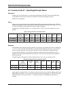
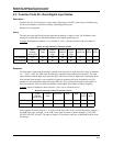
4.5 Function Codes 04 - Read Input Registers
Description
Function code 04(3X references) provides read access to Analog Input modules positioned in ANY Rack
or Slot. All values are in IEEE 32-bit floating point format.
Each Rack is allocated space for a maximum of 16 Slots and each Slot assumes Modules with a maximum
of 8 Channels, which consumes 16 Modbus Register addresses.
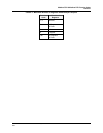
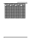
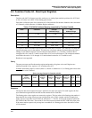
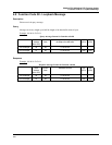
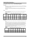
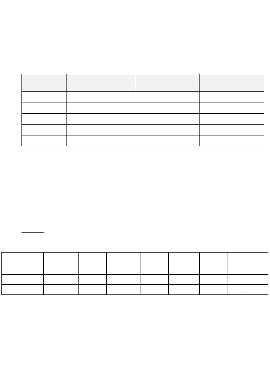
Table 4-7 HC900 AI Address Mapping supported by Function Code 04
Rack Channels Decimal
Address Range
Hex
Address Range
1
1 - 128 1 - 255 0 -FF
2
129 - 256 257 - 511 100 - 1FF
3
257 - 384 513 - 767 200 - 2FF
4
385 - 512 769 - 1023 300 - 3FF
5
513 - 640 1025 - 1279 400 - 4FF
If a request is made to an address that does not exist in the map in Section 1, the controller will honor that
request and return zeros for that address. This behavior will greatly enhance the bandwidth on the link vs.
making several different requests for non-contiguous data elements. (i.e. Consider a controller that is
configured for AI #1 and AI #3 and for some reason AI #2 is an invalid request.) The contiguous method
would allow the read of AI #1 through AI #3 and the data location for AI #2 would be zeros.
Broadcast is not supported.
Query
The query message specifies the starting register and quantity of registers to be read. Registers are
addressed starting at zero: registers 1-16 are addressed as 0-15.
Example:
Read analog inputs #1 and #2 (Rack #1, Module #1) addresses 0-3, as floating point values from
the controller at slave address 1.
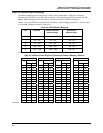
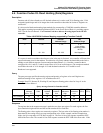
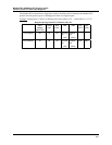
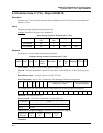
Query message format for function code 04
Slave
Address
(00 for TCP)
Function
Code
Starting
Address
High
Starting
Address
Low
Number
Addresses
High
Number
Addresse
s Low
CRC
(RTU
)
CRC
(RTU)
TCP Example 00 04 00 00 00 04
RTU Example 01 04 00 00 00 04 CRC CRC
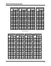
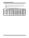
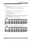
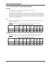
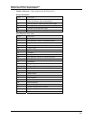
Response
The register data in the response message is packed as two bytes per register. For each register, the first
byte contains the high order bits and the second contains the low order bits.
The floating point values require two consecutive registers. The byte order of the floating point number is
determined by the setting of the byte swap configuration value. In this example, and the examples that
follow, the byte swap order is FP B. Refer to subsection 1.3. The first 16 bits of the response contain the
IEEE MSB of the float value. The second 16 bits of the response contain the IEEE LSB of the float value.
If the master station requests only one register at an address of a floating point value, then half of a float
will be returned.