


Modbus/TCP & Modbus RTU Function Codes
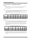
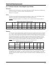
Function Code 01 – Read Digital Output Status
Revision 4 HC900 Hybrid Controller Communications User Guide 21
9/03
Digital I/O Channel to Address Mapping
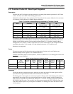
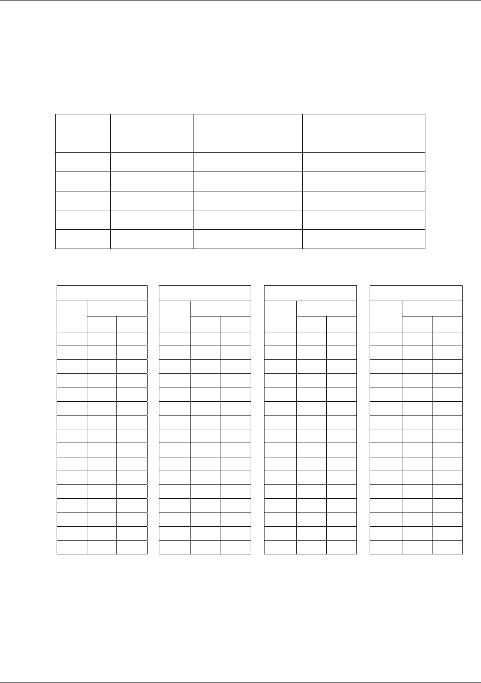
The address mapping provides support for 5 racks of DI or DO modules. Each rack is allocated
addressing for a maximum of 16 slots with 16 channels. The following table defines the rack, slot and
channel address mapping used for DI and DO (each DI/O consumes 1 Modbus bit address):
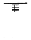
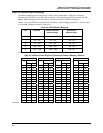
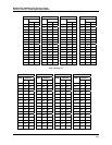
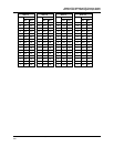
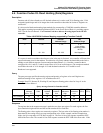
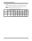
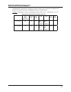
Table 4-5 shows the Modbus Comm Digital I/O Channel to Address Mapping for Rack #1. Refer to Table
4-4 for Address Ranges for Racks #2 through #5.
Table 4-4 DI/DO Address Mapping
Rack
Channels Modbus Decimal
Address Range*
Modbus Hex
Address Range
1
1 - 256 1 – 256 0 - FF
2
257 - 512 257 - 512 100 - 1FF
3
513 - 768 513 – 768 200 - 2FF
4
769 - 1024 769 – 1024 300 - 3FF
5
1025 - 1280 1025 - 1280 400 - 4FF
*Decimal addressing is typically non-zero based for DI/DO access.
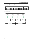
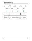
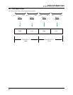
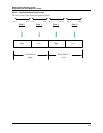
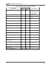
Table 4-5 Modbus Comm Digital I/O Channel to Address Mapping - Rack #1
Slot 1 Slot 2 Slot 3 Slot 4
Address Address Address Address CH#
Dec Hex
CH#
Dec Hex
CH#
Dec Hex
CH#
Dec Hex
16 16 0F 16 32 1F 16 48 2F 16 64 3F
15 15 0E 15 31 1E 15 47 2E 15 63 3E
14 14 0D 14 30 1D 14 46 2D 14 62 3D
13 13 0C 13 29 1C 13 45 2C 13 61 3C
12 12 0B 12 28 1B 12 44 2B 12 60 3B
11 11 0A 11 27 1A 11 43 2A 11 59 3A
10 10 9 10 26 19 10 42 29 10 58 39
9 9 8 9 25 18 9 41 28 9 57 38
8 8 7 8 24 17 8 40 27 8 56 37
7 7 6 7 23 16 7 39 26 7 55 36
6 6 5 6 22 15 6 38 25 6 54 35
5 5 4 5 21 14 5 37 24 5 53 34
4 4 3 4 20 13 4 36 23 4 52 33
3 3 2 3 19 12 3 35 22 3 51 32
2 2 1 2 18 11 2 34 21 2 50 31
1 1 0 1 17 10 1 33 20 1 49 30
Continued