


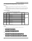
Register Map for Process and Operation Type Variables
Signal Tag Register Map
Revision 4 HC900 Hybrid Controller Communications User Guide 51
9/03
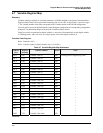
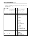
6.9 Signal Tag Register Map
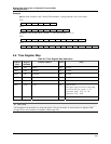
Summary
Signal tags are connected to output pins of function blocks, representing analog or digital parameters, and
are read-only parameters. Digital Signal tags are also represented in floating point, 0.0 for OFF or logic 0,
1.0 for ON or logic 1. The signal tag number in the table corresponds to the signal tag number in the
HC900 Hybrid Control Designer configuration. You will need to access the Hybrid Control Designer
configuration "Tag Information" report to identify the Signal Tag numbers desired.
Note: to convert floating point values (analog or digital) to integer 16, for use with third party touch panels
and associated HMI software, for example, requires the use of the user-defined modbus map for assigning
new modbus addresses and associated data type, configurable in HC Designer, Ver. 2.0 or later.
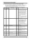
Function Code Support:
Read – Function Code 3
NOTES:
Floating Point in Engineering Units
Digital Signal Tags are represented as 0.0 for OFF, 1.0 for ON.
Access is Read Only
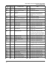
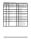
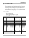
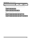
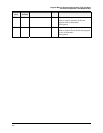
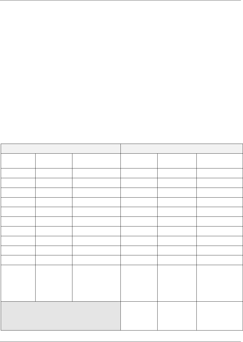
Table 6-9 Signal Tag Register Map Addresses
Legacy HC900 Range
Address
(hex)
Register
(decimal)
Channel Number Address
(hex)
Register
(decimal)
Channel Number
2000 8193 Tagged Signal #1
3B60 15201
Tagged Signal #1
2002 8195 Tagged Signal #2
3B62 15203
Tagged Signal #2
2004 8197 Tagged Signal #3
3B64 15205
Tagged Signal #3
2006 8199 Tagged Signal #4
3B66 15207
Tagged Signal #4
2008 8201 Tagged Signal #5
3B68 15209
Tagged Signal #5
200A 8203 Tagged Signal #6
3B6A 15211
Tagged Signal #6
200C 8205 Tagged Signal #7
3B6C 15213
Tagged Signal #7
200E 8207 Tagged Signal #8
3B6E 15215
Tagged Signal #8
2010 8209 Tagged Signal #9
3B70 15217
Tagged Signal #9
2012 8211 Tagged Signal #10
3B72 15219
Tagged Signal #10
.
.
.
27CF
.
.
.
10192
.
.
.
Tagged Signal
#1000
42CB
17099
.
.
.
Tagged Signal
#1000
42CD
17101
Tagged Signal
#1001
.
.