


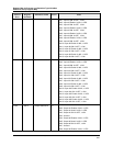
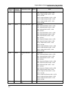
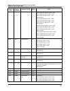
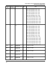
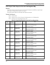
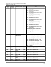
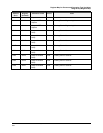
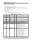
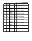

Register Map for Process and Operation Type Variables
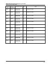
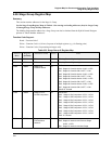
Stage Group Register Map
86 HC900 Hybrid Controller Communications User Guide Revision 4
9/03
Address
(hex)
Register
(decimal)
Parameter Name Access Notes
0=NO, 1=YES
Bit 2: Stage #1 Error with Interlocks
0=NO, 1=YES
Bit 3: Stage #2 Interlock with Previous Stage
0=NO, 1=YES
Bit 4: Stage #2 Interlock with Next Stage
0=NO, 1=YES
Bit 5: Stage #2 Error with Interlocks
0=NO, 1=YES
Bit 6: Stage #3 Interlock with Previous Stage
0=NO, 1=YES
Bit 7: Stage #3 Interlock with Next Stage
0=NO, 1=YES
Bit 8: Stage #3 Error with Interlocks
0=NO, 1=YES
Bit 9: Stage #4 Interlock with Previous Stage
0=NO, 1=YES
Bit 10: Stage #4 Interlock with Next Stage
0=NO, 1=YES
Bit 11: Stage #4 Error with Interlocks
0=NO, 1=YES
Bit 12 - 15: Unused
6207 25096 Stage #1-4 Output
Status (Request)
R
Bit Packed:
Bit 0: Stage #1 Output Enable: 0=NO, 1=YES
Bit 1: Stage #1 Output ON: 0=OFF, 1=ON
Bit 2: Stage #2 Output Enable: 0=NO, 1=YES
Bit 3: Stage #2 Output ON: 0=OFF, 1=ON
Bit 4: Stage #3 Output Enable: 0=NO, 1=YES
Bit 5: Stage #3 Output ON: 0=OFF, 1=ON
Bit 6: Stage #4 Output Enable: 0=NO, 1=YES
Bit 7: Stage #4 Output ON: 0=OFF, 1=ON
Bit 8-15: Unused
6208 25097 Stage #1 ON
Setpoint
R/W Floating Point in Engineering Units
620A 25099 Stage #2 ON
Setpoint
R/W Floating Point in Engineering Units
620C 25101 Stage #3 ON
Setpoint
R/W Floating Point in Engineering Units
620E 25103 Stage #4 ON
Setpoint
R/W Floating Point in Engineering Units
6210 25105 Stage #1 OFF
Setpoint
R/W Floating Point in Engineering Units
6212 25107 Stage #2 OFF
St it
R/W Floating Point in Engineering Units