


Register Map for Process and Operation Type Variables
Analog Input Value Register Map - Function Code 04
48 HC900 Hybrid Controller Communications User Guide Revision 4
9/03
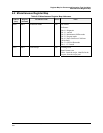
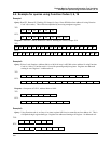
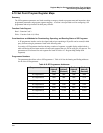
6.6 Analog Input Value Register Map - Function Code 04
Summary
Used to access analog input parameters positioned in any Rack or Slot.
Analog Input Example: AI1 through AI64. The mapping is with respect to card position starting with the
first card slot position (numbered 1 through 16, starting at the lower left) with an analog input card. Since
each card has 8 inputs, the first module position with analog inputs (I/O card Type 1) would be AI1 thru
AI8. If the next AI card is in slot 2 this would be AI9 thru AI16 and so on.
Function Code Support:
Reads – Function Code 04 (positioned in any Rack or Slot)
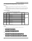
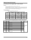
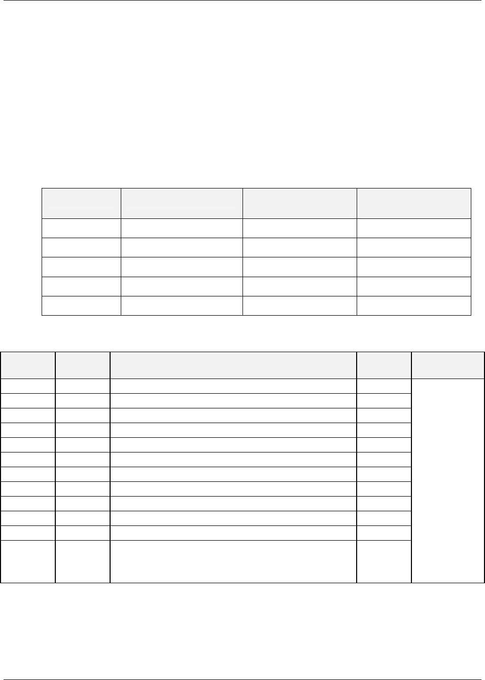
Table 6-5 HC900 AI Address Mapping supported by Function Code 04
Rack Channels Decimal
Address Range
Hex
Address Range
1
1 - 128 1 – 255 0 -FF
2
129 - 256 257- 511 100 - 1FF
3
257 - 384 513 – 767 200 - 2FF
4
385 - 512 769 – 1023 300 - 3FF
5
513 - 640 1025 - 1279 400 - 4FF
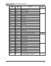
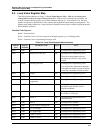
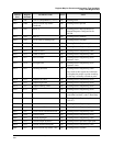
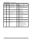
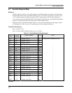
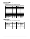
Table 6-6 Analog Input Value Register Map Addresses for Rack #1 - Function Code 04
Address
(hex)
Register
(decimal)
Channel Number Access Notes
0 1 Analog Input #1 R
2 3 Analog Input #2 R
4 5 Analog Input #3 R
6 7 Analog Input #4 R
8 9 Analog Input #5 R
A 11 Analog Input #6 R
C 13 Analog Input #7 R
E 15 Analog Input #8 R
10 17 Analog Input #9 R
12 19 Analog Input #10 R
14 21 Analog Input #11 R
16 23 Analog Input #12 R
: : :
C0 193 Analog Input #96 R
Floating Point
in Engineering
Units.