


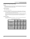
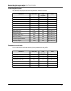

Register Map for Process and Operation Type Variables
Segment Register Map
Revision 4 HC900 Hybrid Controller Communications User Guide 61
9/03
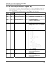
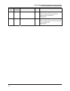
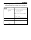
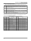
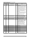
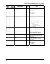
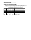
6.14 Segment Register Map
The table below describes the registers that are part of a setpoint programmer segment. To determine the
actual register address for a parameter within a segment, add the register offset to the start address of the
segment.
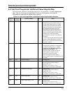
Table 6-16 Segment Register Map Addresses
Register
Offset within
Segment
Parameter Name Access Notes
0 Ramp/Soak Segment
Guaranteed Soak
Enable
R/W Bit Packed
Bit 0: 1 = ramp segment; 0=soak segment
Bit 1: 1 = guaranteed soak enabled
0 = guaranteed soak disabled
Bit 0 is ignored in the hold mode.
Writing to this register is not permissible in the run mode.
1 Events R/W Bit Packed
Bit 0: Event #1
: :
Bit 15: Event #16
0: Event OFF 1: Event ON
Writing to this register is only permissible in reset or ready
mode.
2 Time or Rate R/W Floating Point in time units configured for the set point
programmer
Writing to this register is not permissible in the run mode.
4 Ramp or Soak value R/W Floating Point
Writing to this register is not permissible in the run mode.
6 Soak value for
auxiliary output (use
“Time or Rate” for
duration)
R/W Floating Point
Writing to this register is not permissible in the run mode.