


Introduction
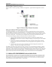
Modbus RTU RS232/RS485 Communication Ports
Revision 4 HC900 Hybrid Controller Communications User Guide 5
9/03
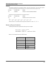
These instruments DO NOT emulate any MODICON type device. The Modbus RTU specification is respected in
the physical and data link layers. The message structure of the Modbus RTU function codes is employed and
standard IEEE 32-bit floating point and integer formats are used. Data register mapping is unique to these
instruments. The definition in Table 6-1 is the register mapping for the HC900-C30 and HC900-C50 and the
corresponding parameter value within those instruments.
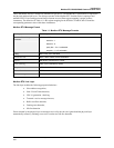
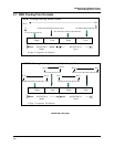
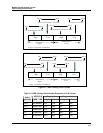
Modbus RTU Message Format
Table 1-1 Modbus RTU Message Formats
Coding system 8 bit binary
Number of data bits per
character
10, 11, or 12 Bits
start bits - 1
data bits - 8
parity bits – 0 or 1 selectable
stop bits – 1 or 2 selectable
Parity None, odd, even selectable
Bit transfer rate 9600, 19200, 38400, 57600 Selectable
Duplex Half duplex Transceiver or TX/RX
Error checking CRC (cyclic redundancy check)
Polynomial (CRC-16 10100000000001)
Bit transfer order LSB first
End of message Idle line for 3.5 or more characters (>1.82 msec for 19200).
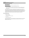
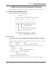
Modbus RTU Link Layer
The link layer includes the following properties/behaviors:
• Slave address recognition,
• Start / End of Frame detection,
• CRC-16 generation / checking,
• Transmit / receive message time-out,
• Buffer overflow detection,
• Framing error detection,
• Idle line detection.
Errors detected by the physical layer in messages received by the slave are ignored and the physical layer
automatically restarts by initiating a new receive on the next idle line detection.