


Modbus/TCP & Modbus RTU Function Codes
Function Code 01 – Read Digital Output Status
20 HC900 Hybrid Controller Communications User Guide Revision 4
9/03
4.2 Function Code 01 – Read Digital Output Status
Description
Function code 01 (0X references) is used to read a digital output’s ON/OFF status of the HC900 using
16 bit addressing for DO access and data is returned in a binary format mapped into bytes.
Broadcast is not supported.
Query
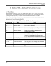
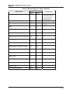
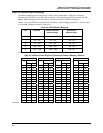
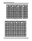
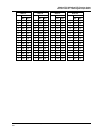
The query message specifies the starting Digital Output (DO) and the quantity of DOs to read. The DO
address in the message is based on the rack slot and channel number of the digital output being read. Table
4-5 shows the Modbus Comm Digital I/O Channel to Address Mapping.
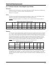
Example Query: Read DO channels 1 to 16, located in Rack #1, Slot #1; from the controller with slave
address 1.
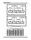
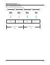
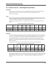
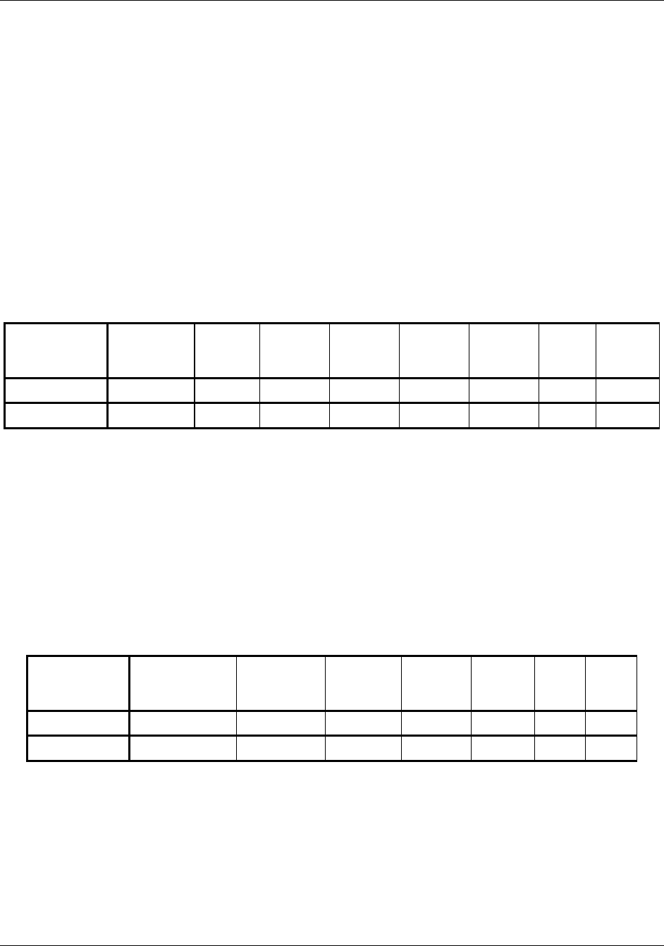
Query message format for function code 01
Slave
Address
(00 for TCP)
Function
Code
Starting
Address
High
Starting
Address
Low
Number
DO
High
Number
DO
Low
CRC
(RTU)
CRC
(RTU)
TCP Example 00 01 00 00 00 10
RTU Example 01 01 00 00 00 10 CRC CRC
Response
The DO status in the response message is packed as one DO per bit of the data field. Status is indicated as:
1 = ON; 0 = OFF. The LSB of the first data byte contains the DO addressed in the query. The other DOs
follow toward the high order end of this byte, and from low order to high order in subsequent bytes.
If the returned DO quantity is not a multiple of eight, the remaining bits in the final data byte will be
padded with zeros (toward the high order end of the byte). The byte count field specifies the quantity of
data bytes returned.
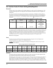
Example Response: DO channels 2 and 6 located in Rack #1, Slot #1 are on; all others are off.
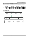
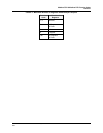
Response message format for function code 01
Slave
Address
(00 for TCP)
Function
Code
Byte
Count
Data Data CRC
(RTU)
CRC
(RTU)
TCP Example 00 01 02 22 00
RTU Example 01 01 02 22 00 CRC CRC
In the response the status of DOs 1 - 8 is shown as the byte value 22 hex, or 0010 0010 binary. DO 8 is the
MSB of this byte, and DO 1 is the LSB. Left to right, the status of DO 8 through 1 is: OFF-OFF-ON-OFF-
OFF-OFF-ON-OFF. The status of DOs 9 - 16 are shown a 00hex, or 0000 0000 with the same bit
ordering.