


IBM System Storage DR550 Version 3.0 ------17 March 2006 Page 35
IBM Storage Systems Copyright © 2006 by International Business Machines Corporation
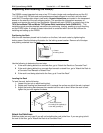
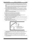
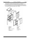
19. Remove the two rack-mounting plates from the marked areas.
20. At the marked location of the threaded rack-mounting bolt holes, drill four clearance holes
into the concrete floor. Each clearance hole should be approximately one inch deep. This
allows the rack-mounting bolts enough room to protrude past the thickness of the mounting
plate.
Note: You must use a minimum of two anchor bolts for each rack-mounting plate to securely
attach the plate to the concrete floor. Because some of the holes in each rack-mounting
plate may align with concrete reinforcement rods embedded in the concrete, some of the
rack-mounting plate holes may not be usable.
21. Select at least two suitable hole locations for each rack-mounting plate bolt. The selected
locations should be as close to the threaded bolt holes as possible. Be sure that the holes
selected at the rear of the rack are accessible. Drill holes at the selected locations into the
concrete floor.
Note: The size of the anchor bolts and concrete anchors must be determined by the
mechanical contractor doing the installation.
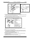
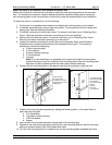
22. Position the front-mounting plate over the concrete anchors.
23. Securely bolt the front rack-mounting plate to the concrete floor.
24. Position the rear-mounting plate over the concrete anchors.
25. Securely bolt the rear rack-mounting plate to the concrete floor.
Note: The size of the anchor bolts and concrete anchors must be determined by the
mechanical contractor doing the rack-mounting plate installation.
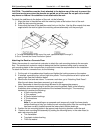
26. Position the rack over the rack-mounting plates.
27. Insert each of the rack-mounting bolts through a flat washer, a plastic isolator bushing and a
thick washer, and through a leveling foot.
28. Align the four rack-mounting bolts with the four tapped holes in the two mounting plates and
turn three to four rotations.
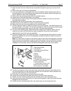
29. Tighten the locking screw on each caster.
30. Adjust the leveling feet downward as needed until the rack is level. When the rack is level,
tighten the jam nuts against the base of the rack.
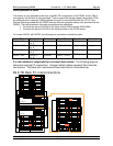
1
2
3
1 Rack Front (base)
2 Leveling Foot (quantity 4)
3 Jam Nut (quantity 4)
31. If you have multiple racks that are connected in a suite (bolted to each other), go to
“Installing Multiple Racks Connected in a Suite”. Otherwise, torque the four bolts to 40-50 ft-
lbs (54-67 nm).
32. If you are not installing doors on your rack, install the top, left, and right trim panel.
33. Connect the power distribution system as described in “Connect the Power Distribution
System”.
34. After all racks are bolted down, go to “Attaching Front or Rear AC Electrical Outlet”.
35. If you are not going to attach a front electrical outlet and you are installing rack doors, go to
“Attaching Rack Doors”