


IBM System Storage DR550 Version 3.0 ------17 March 2006 Page 40
IBM Storage Systems Copyright © 2006 by International Business Machines Corporation
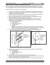
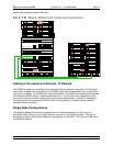
Cabling between the Racks
This section is only applicable to the dual node 89.6 TB configuration of the DR550. At 44.8 TBs of
raw capacity, the first rack is fully populated. Thus to expand the storage capacity beyond 44.8 TBs,
an additional rack is required. Cabling between the racks is accomplished with two LC-LC Fibre
Channel Cables provided with the DR550 and two Ethernet crossover cables (also provided with the
DR550). The cabling between the racks accomplishes two objectives:
• Connects the second DS4100 to the Fibre channel SAN switches (2005-H08s)
• Connects the second DS4100 to the Ethernet ports on the P5 520 server
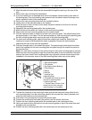
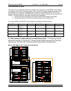
To connect RACK1 with RACK2, the following four connections should be made:
Rack / EIA Device Connector Rack / EIA Device Connector
RACK2 / EIA1 DS4100_2
Ctrl_A
Host 1 RACK1 / EIA17 SAN Switch_1 Port_3
RACK2 / EIA1 DS4100_2
Ctrl_B
Host 1 RACK1 / EIA23 SAN Switch_2 Port_3
RACK2 / EIA1 DS4100_2
Ctrl_A
Ethernet RACK1 / EIA13
DR_Engine_1
Ethernet
RACK2 / EIA1 DS4100_2
Ctrl_B
Ethernet RACK1 / EIA13
DR_Engine_1
Ethernet
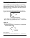
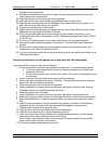
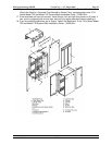
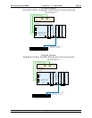
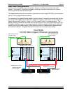
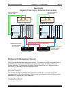
It is the customer’s responsibility to connect these cables. The following diagram
shows the required FC connections. Orange (dotted) cables represent fibre channels
connections. The black (thin) connections have been done in manufacturing.
89.6 TB Rack FC Interconnections
EXP100_2,1
DS4100_2
EXP100_2,2
IN OUT
EXP100_2,3
IN OUT
IN
OUT
IN
OUT
IN OUT
IN
OUT
EXP100_2,4
EXP100_2,5
IN OUT
EXP100_2,6
IN OUT
IN
OUT
IN
OUT
IN OUT
IN
OUT
EXP100_2,7
IN OUT
IN OUT
EXP100_1,1
EXP100_1,2
IN
OUT
EXP100_1,3
IN OUT
IN
OUT
IN OUT
IN OUT
IN OUT
EXP100_1,4
EXP100_1,5
IN OUT
EXP100_1,6
IN OUT
IN
OUT
IN OUT
IN
OUT
IN OUT
EXP100_1,6
IN OUT
IN
OUT
Switch_2
0 1 2 3 4 5 6 7
Switch_1
0 1 2 3 4 5 6 7
DRS_Engine_2
1 2 3 4 5 6
A
B
DRS_Engine_1
1 2 3 4 5 6
A
B
7310-CR3
7316-TF3
DS4100_1