


IBM System Storage DR550 Version 3.0 ------17 March 2006 Page 46
IBM Storage Systems Copyright © 2006 by International Business Machines Corporation
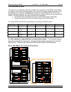
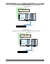
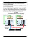
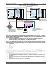
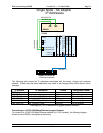
Dual Node - All Configurations
Cat 5 cable connected to USB
Conversion Option cable (p/n
78P5833 - 7316-TF3 FC 4269 ) -
IBM Supplied
10/100/1000 (T6)
HMC1
HMC2
System
board
10/100/1000 (T5)
USB1 (T7)
USB2 (T8)
Pwr GXT135p Graphics
Adapter - Slot 2
2 Port 10/100/1000 Ethernet
TX PCI-X Adapter - Slot 3
2 Gb Fibre channel
Adapter - Slot 4
2 Gb Fibre Channel
Adapter - Slot 5
7316-TF3 Console with
KVM switch (FC 4202)
and IBM supplied video,
keyboard and mouse
cables (FC 4242)
7310-CR2 HMC
P5 520 #2 (DRS_Engine_2)
Netbay LCM
P5 520 #1 (DRS_Engine_1)
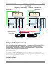
Cat 5 cable connected to CT2
Conversion Option cable (p/n 32
P
1637)
connected to Out port in HMC server -
IBM Supplied
Cat 5 cable connected to USB
Conversion Option cable (p/n
78P5833 - 7316-TF3 FC 4269 ) -
IBM Supplied
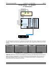
Modular phone cable (IBM
supplied) plugged into right
side phone jack in HMC and
connected to analog phone
jack (supplied by customer)
Standby
Ethernet Crossover
cables - IBM Supplied
10/100/1000 (T6)
HMC1
HMC2
System
board
10/100/1000 (T5)
USB1 (T7)
USB2 (T8)
Pwr GXT135p Graphics
Adapter - Slot 2
2 Port 10/100/1000 Ethernet
TX PCI-X Adapter - Slot 3
2 Gb Fibre channel
Adapter - Slot 4
2 Gb Fibre Channel
Adapter - Slot 5
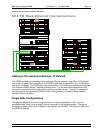
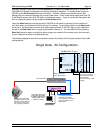
As an option, you can attach an external monitor using the serial ports on the P5 520s. To interact
with the system software interfaces or to run diagnostics from a DVD-RAM using an external device,
you will need to do the following:
• Connect a terminal (or PC) to the serial port FS1 (on the front of the unit) using a null-
modem cable (RJ45 to 9 pin Serial cable which is provided by IBM)
Your PC may need to use an emulator, such as HyperTerminal, often supplied with Windows family
operating systems. Set the emulation mode to vt100 and use the following communication settings:
• 19200 baud
• 8 bit
• 1 stop bit
• No parity
• Xon/Xoff
The following procedure is to connect the ASCII (tty) terminal (or PC) to the P5 520 (this is provided
as information only as it is recommended that you use the integrated console for all DR550
management activity:
1. Before doing this step, read and understand “Read the Safety Notices”.
2. This system drawer is equipped with serial port 1 located in the front (FS1) and rear (S1) of
the system.
3. Use an RJ-45 to 9-pin serial null modem cable (IBM supplied) to connect to the front serial
port FS1.
4. When using FS1, the rear serial port 1 is deactivated.