


IBM System Storage DR550 Version 3.0 ------17 March 2006 Page 59
IBM Storage Systems Copyright © 2006 by International Business Machines Corporation
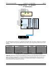
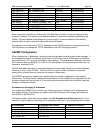
192.168.4.103 drs_DS40002_ctrlA DS4100 Do not change
192.168.5.104 drs_DS40002_ctrlB DS4100 Do not change
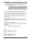
DRS_Engine_2
192.168.1.23 drs_engine2_boot AIX To be changed
192.168.2.11 drs_engine2_stdby AIX To be changed
192.168.3.11 drs_engine2_hrtbeat AIX / HACMP Do not change
192.168.4.24 drs_engine2_DS40001_ctrlA AIX Do not change
192.168.5.26 drs_engine2_DS40001_ctrlB AIX Do not change
192.168.4.101 drs_DS40001_ctrlA DS4100 Do not change
192.168.5.102 drs_DS40001_ctrlB DS4100 Do not change
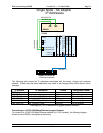
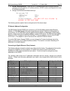
Preconfigured TCP/IP addresses for 10/100/1000 Ethernet
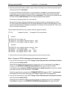
Each connection should be to a different 10/100/1000 Ethernet switch, which are elements of the
customer’s network. The reason to use different switches is to enhance network availability to the
DR550. The boot network is the network for normal usage. The second network is the standby
network which is used in case of problems with the boot network.
It is important not to change the TCP/IP addresses on the P5 520 servers for the attachment of the
DS4100 servers nor change the TCP/IP addresses on the DS4100 storage servers.
HACMP Configuration
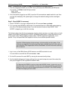
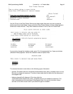
When changing the IP addresses, you should use the integrated console to make these changes. If
the integrated console is not working, the serial port on the front of each P5 520 server is available
for connection to a TTY terminal (provided by the customer). The console works best with a physical
ASCII terminal such as IBM 3151 or vt100 or a PC workstation running a terminal emulator such as
hyperterm, emulating vt100.
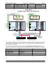
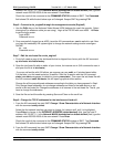
HACMP heartbeat information is exchanged between the two nodes through the host bus adapters
(Ethernet) in slot 3 of the P5 520s. This connection is used to monitor the network and server,
ensuring that a failure does not cause an interruption in data access.
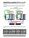
The HACMP configuration needs to be modified when the solution is deployed in the customer
environment. The boot and the standby addresses will have to be modified to be compatible with the
customer subnet that they connect to. It is a best practice recommendation to have them (boot and
standby) on different subnets.
Procedures for Changing IP Addresses
To configure the DR550 for the use with your network you have to change five IP addresses from
their factory settings. The changes are made on both P5 520 servers. No changes are needed on
the DS4100 or the 2005-B16.
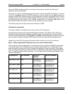
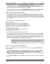
The following table, which was also provided in the Site Preparation and Planning Section of this
document, may be helpful in recording the IP addresses to be used in your operational environment.
IP Description IP Address from Factory IP Address in Network
Drs_engine1_boot 192.168.1.21
Drs_engine1_stdby 192.168.2.10
Drs_engine2_boot 192.168.1.23
Drs_engine2_stdby 192.168.2.11
Drs_cluster_svc 192.168.1.22