


IBM System Storage DR550 Version 3.0 ------17 March 2006 Page 47
IBM Storage Systems Copyright © 2006 by International Business Machines Corporation
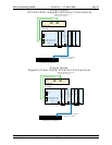
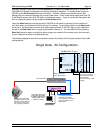
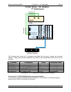
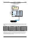
5. Use a 9-pin to 9-pin serial converter cable (customer supplied) when connecting to the rear
serial port 1.
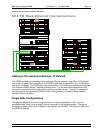
An ASCII (tty) terminal must be used to configure both P5 520 servers. If you have a single terminal,
you may connect it to one P5 520 and configure the server. Then connect it to the other P5 520
server and configure it. Thus only one terminal is needed as the console in setting up the DR550.
For convenience, the front (FS1) serial port is often preferred.
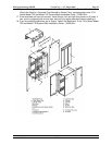
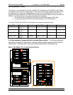
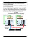
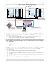
Dual Node Configurations: Note that P5 520 engine_1 (also referred to as drs_engine_1) is
located in Rack1 position 13. P5 520 engine_2 (also referred to as drs_engine_2) is located in
Rack1 position 19. Also refer to the Cabling between the Racks section for an illustration of the
location of engine_1 and engine_2. It is recommended that you disconnect the cable at the server
side when the console is not in use.
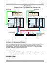
Connecting AC Power
Check the AC Outlets
Refer to the 7014 Series Model T00 and Model T42 Installation Guide for additional information in
the installation and setup of the 7014 Series Model T00 rack.
Before plugging the rack into the AC power source, do the following checks on the AC power
source.
CAUTION: Do not touch the receptacle or the receptacle faceplate with anything other than
your test probes before you have met the requirements in step 8.
1. Turn off the branch circuit breaker for the ac power outlet that the rack will plug into. To the
circuit breaker switch, attach tag S229-0237, which reads “Do Not Operate”.
Note: All measurements are made with the receptacle face plate in the normal installed
position.
2. Some receptacles are enclosed in metal housings. For this type of receptacle, do the
following:
a. Check for less than 1 volt from the receptacle case to any grounded metal structure
in the building, such as a raised-floor metal structure, water pipe, building steel, or
similar structure.
b. Check for less than 1 volt from the receptacle ground pin to a grounded point in the
building.
Note: If the receptacle case or face plate is painted, be sure the probe tip penetrates
the paint and makes good electrical contact with the metal.
c. Check the resistance from the receptacle ground pin to the receptacle case. Check
resistance from the ground pin to the building ground. The readings should be less
than 1.0 ohm, which indicates the presence of a continuous grounding conductor.
3. If any of the three checks made in sub step 2 are not correct, remove the power from the
branch circuit and make the wiring corrections; then check the receptacle again.
Note: Do not use a digital multi-meter to measure grounding resistance in the following
steps.
4. Check for infinite resistance between the ground pin of the receptacle and each of the phase
pins. This is a check for a wiring short to ground or a wiring reversal.
5. Check for infinite resistance between the phase pins. This is a check for a wiring short.
CAUTION: If the reading is other than infinity, do not proceed! Have the customer
make necessary wiring connections before continuing. Do not turn on the branch
circuit CB until all the above steps are satisfactorily completed.