


IBM System Storage DR550 Version 3.0 ------17 March 2006 Page 48
IBM Storage Systems Copyright © 2006 by International Business Machines Corporation
6. Turn on the branch circuit breaker. Measure for the appropriate voltages between phases. If
no voltage is present on the receptacle case or grounded pin, the receptacle is safe to touch.
7. With an appropriate meter, verify that the voltage at the ac outlet is correct.
8. Verify that the grounding impedance is correct by using the ECOS 1020, 1023, B7106,
C7106, or an appropriately approved ground-impedance tester.
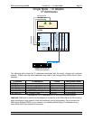
Cabling AC
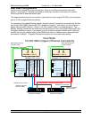
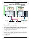
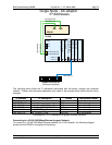
The DR550 rack(s) have sets of AC power rails (left and right) traversing vertically in the rear of the
rack cabinet. Each rail in a set should be connected to a different AC power feed if that is available.
This is to enhance the availability of the rack components. Each power source should be 220V or
200V single phase rated at 30 amps.
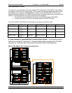
For the 5.6 and 11.2 TB configurations, there are two power rails. For the 22.4 and 44.8 TB offering,
there are four power rails. For the 89.6 TB offering, there will be eight power rails, 4 per rack. Power
cords are shipped with each rack (one per rail) to enable cabling to AC power above or below each
rack. Power cords come with NEMA L6-30 connectors.
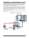
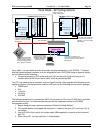
Each device in the rack is connected to the AC Power Rails. When shipped from the factory each
component will have the AC power switch in the OFF position. The SAN Switch (one in the single
node configuration or two in the dual node configuration) do not have an AC switch, and thus will be
powered up as soon as the rails become energized.
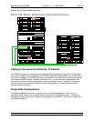
Power on Sequence
The devices in the rack should be powered on in the following sequence:
1. SAN Switch(es) (Before proceeding to step 3, confirm that the SAN Switch(es) have
completed their power on sequencing. This is indicated with a green light showing for
power.)
2. DS4000 EXP100 Serial ATA drives (0 to 14 devices depending on the disk capacity
installed)
3. DS4100 (single device except for 89.6 TB configurations which has two)
4. P5 520 #1 (located at EIA 13-16 in the rack)
5. P5 520 #2 (located at EIA 19-22 in the rack – this is only present in the dual node
configurations)
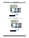
Similarly, should power need to be shut down, the reverse of the power on sequence should be
followed (once the applications and operating systems have been shutdown):
1. P5 520 #2 (located at EIA 19-22 in the rack – this is only present in the dual node
configurations)
2. P5 520 #1 (located at EIA 13-16 in the rack)
3. DS4100 (single device except for 89.6 TB configurations which has two)
4. DS4000 EXP100 Serial ATA drives (0 to 14 devices depending on the disk capacity
installed)
5. SAN Switch(es)
Connect the Drawer and Device Cables
The DR550 rack(s) are preconfigured at the factory with all drawers and device cables installed. To
check out the system, refer to the RS/6000 and eServer pSeries Diagnostics Information for Multiple
Bus Systems and follow the instructions in the installation checkout procedure.