


IBM System Storage DR550 Version 3.0 ------17 March 2006 Page 38
IBM Storage Systems Copyright © 2006 by International Business Machines Corporation
30. Using your anchor bolts, secure the rear rack-mounting plate on top of the raised floor and
through to the concrete floor.
31. Replace all raised panels that may have been removed when aligning and securing the
anchor bolts to the concrete floor.
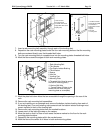
32. Align the rack over the front and rear-mounting plates.
33. Insert each of the rack-mounting bolts assemblies through a leveling foot.
34. Align the rack-mounting bolts with the threaded holes in each rack-mounting plate. Turn
each rack-mounting bolt three to four rotations.
36. Tighten the locking screw on each caster.
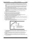
37. Adjust the leveling feet downward as needed until the rack is level. When the rack is level,
tighten the jam nuts against the base of the rack.
38. If you have multiple racks that are connected as a suite (bolted to each other), go to
“Installing Multiple Racks Connected in a Suite”. Otherwise torque the four bolts to 40-50 ft-
lbs (54-67 nm).
39. If you are not installing doors on your rack, install the top, left, and right trim panel.
40. Connect the power distribution system as described in “Connect the Power Distribution
System”
41. After the rack is bolted down and you are going to attach a front electrical outlet, go to
“Attaching Front or Rear AC Electrical Outlet”.
42. If you are not going to attach a front electrical outlet and you are installing rack doors, go to
“Attaching Rack Doors”.
Connecting the Racks in a Suite (applies only to dual node 89.6 TB Configuration)
If you are installing a suite of racks, do the following:
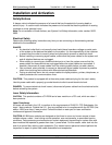
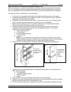
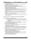
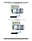
1. If they are installed, remove the side panels from each rack. To remove the side panels:
a. Lift the two panel-release tabs up. See the following illustration for the two panel
release tab locations.
b. Pull the panel up and away from the rack chassis. This motion will release the panel
from the two
2. Lower J brackets. Store the side panels away from the work area.
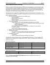
3. Remove the two Z brackets and the two J brackets. These brackets are used to hang the
side panels. See the following illustration.
4. Stand facing the first rack and locate the right side.
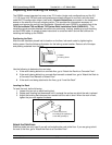
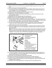
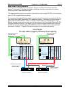
5. Install a standoff in the upper-left corner and lower-right corner of the first rack. See the
following illustration for standoff placement locations.
6. Locate the second rack’s left side.
7. Install a standoff in the upper-left corner and lower-right corner of the second rack.
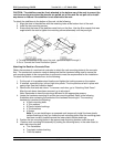
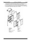
8. Attach the long foam strip as shown in the following illustration. Position the racks together.
9. Align the standoff holes. To align the standoff holes, you may have to adjust the leveling
feet.
10. Install a screw and washer in all four standoff hole positions, as shown in the following
illustration, but do not tighten. After the racks are bolted together, level the racks.
11. Tighten the four screws in the standoff holes.
12. Install the trim pieces that fit between the front and back racks.
13. Install the trim piece that fits on top and between the racks.
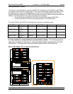
14. Install rack filler panels above and below the installed system drawers. The filler panels
cover and seal the open areas at the front of the rack(s).
Note: All open areas located in the front of the rack must also be sealed to ensure that
proper airflow within the rack is maintained.
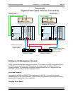
15. Connect the cables that go between the racks.