


IBM System Storage DR550 Version 3.0 ------17 March 2006 Page 41
IBM Storage Systems Copyright © 2006 by International Business Machines Corporation
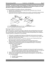
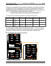
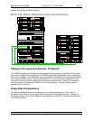
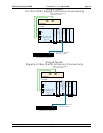
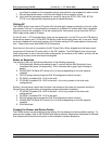
The following diagram shows the required Ethernet connections (green solid lines) that must be
done by the customer between the racks.
8 9 .6 T B R a c k E th e rn e t In te rc o n n e c tio n s
EX P100 _1,1
S witch_ 2
0 1 2 3 4 5 6 7
S witch_ 1
0 1 2 3 4 5 6 7
DR S_E ngine_1
1 2 3 4 5 6
A
B
7310-C R 3
73 16-TF 3
DS 41 00 _1
EX P100_1,2
IN
O U T
EX P100_1,3
IN O U T
IN O U T
IN
O UT
IN O U T
IN O U T
E XP100_1,4
E XP100_1,5
IN O U T
EX P100 _1 ,6
IN O U T
IN O U T
IN O U T
IN O U T
IN
O UT
E XP100_1,6
IN O UT
IN O U T
E XP100_2,1
D S41 00_ 2
EX P100 _2,2
IN O U T
EX P100 _2 ,3
IN O U T
IN O U T
IN
O UT
IN O U T
IN
O UT
EX P100_2,4
EX P100_2,5
IN O U T
EX P100_2,6
IN O U T
IN O U T
IN O U T
IN O U T
IN O UT
EX P100_2,7
IN
O UT
IN O U T
D RS_E ngine_2
1 2 3 4 5 6
A
B
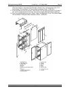
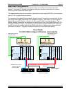
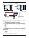
Cabling to the customer’s Ethernet / IP Network
The DR550 provides for connecting to the customers Ethernet network using either 10/100 copper
connections or gigabit fibre connections. For DR550 single node configurations, only one Ethernet
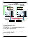
connection is needed. For DR550 dual node configurations, four Ethernet connections are required
(this enables HACMP failover if network problems occur). For the dual node configurations, two
connections should be made to each of two customer provided subnets. Typically, it is expected
that the customer will connect the DR550 to their existing network, including existing customer
provided Ethernet switches.
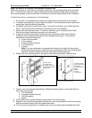
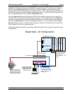
Single Node Configurations
The following diagrams show the connections from an Ethernet perspective. With only one
processing node, there is only a single Ethernet connection to the existing network. The type of
connection (copper or fiber optic) is based on the adapter in the DR550. This choice is made when
the DR550 is ordered.