


SmartConnect User’s Guide
BMD00082, February 2009 Chapter 4: Stacking
49
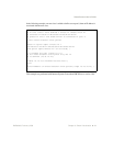
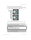
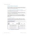
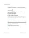
6. Physically connect the Stack Trunks in a bidirectional ring topology.
It is recommended that two 10Gb external ports on each switch are dedicated to stacking. As
shown in Figure 4-A, starting with the Master switch, connect each switch in turn to the next.
Connect the last Member switch back to the Master to complete the ring.
Figure 4-A Example of Stacking Connections
Once the stack trunks are connected, the switches perform low-level stacking configuration.
Note – It is recommended not to disconnect and reconnect the stack links after the stack is
formed. If the stack links are disconnected, stack operation can become unstable as the stack
reconfigures, and traffic can be disrupted, causing data loss.
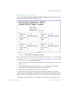
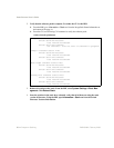
7. On the designated Master switch, configure the Master interface for the stack.
Note – The mif menu is available only on the Master switch once the stacking mode has been
set (Step 4) and the switch has been rebooted (Step 5).
>> # cfg/stack/mif
>> Master Switch Interface# addr 10.10.1.1
>> Master Switch Interface# mask 255.255.0.0
>> Master Switch Interface# gw 10.10.20.2
Server
Server
Server
Server
Member
Switch
Member
Switch
Blade Server Chassis 2
Server
Server
Server
Server
Member
Switch
Master
Switch
Blade Server Chassis 1
Switches
connected in
bidirectional
ring topology