


SmartConnect User’s Guide
BMD00082, February 2009 Chapter 4: Stacking
51
Binding Members to the Stack
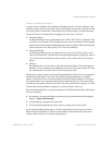
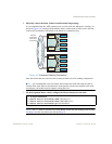
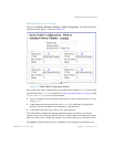
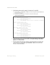
Choose menu System Settings > Stacking > Switch Configuration. The Stack Switch Con-
figuration window appears, as shown in Figure 4-C.
Figure 4-C Stack Switch Configuration Window
Each switch in the stack is represented by an Attached Switch Number (asnum) and a Config-
ured Switch Number (csnum) as explained in “Viewing Stack Connections” on page 50. Both
asnum 1 and csnum 1 are reserved for the Master.
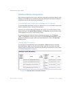
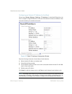
Select an attached switch in the Bind asnum drop-down list to bind the switch to it’s asso-
ciated csnum.
In the Backup Switch drop-down list, select a csnum for a Backup switch (optional)
which will assume the Master role if the Master switch should fail.
In the Stack Name field, enter a name for the stack (optional).
The UUID and Bay Number fields display information about the location of configured
switches and are not configurable. The UUID is the Unit ID number of the blade server chassis
where the switch resides, and the Bay Number is the switch’s physical bay within the chassis.
Click Apply to make the changes active, and Save to retain changes beyond reboot cycles.