Intel
®
31154 133 MHz PCI Bridge Design Guide Design Guide 19
Terminations
Terminations 4
This chapter details all the recommended Intel
®
31154 133 MHz PCI Bridge terminations required
for the different operating modes.
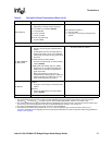
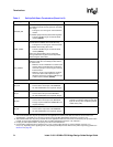
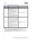
The chapter provides the recommended pull-up and pull-down terminations for a 31154 layout.
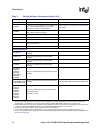
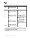
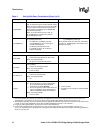
Table 5 lists these 31154 termination values. Note that for motherboards, the PCI Local Bus
Specification, Revision 2.3 requires that the PCI signals provide the termination resistors.
Table 5. Pull-Up/Pull-Down Terminations (Sheet 1 of 9)
Signal Pull-Up/Pull-Down or Termination (See Note 1) Comments
PCI Reset
P_RST# Connect to bus RST# signal on primary PCI bus.
S_RST#
Connect to bus RST# signal on secondary PCI
bus.
Primary PCI Signals
P_AD[31:0] Connect to primary PCI bus AD[31:0].
P_AD[63:32]
For 64-bit primary PCI bus:
• Connect to the AD[63:32] bits of the primary
PCI bus.
For 32 bit Primary PCI Bus:
• Pull up through individual external resistors
(see Note 2 and Note 3).
P_CBE[3:0]
Connect to the CBE[3:0}# bits of the primary PCI
bus.
P_CBE[7:4]#
For 64-bit primary PCI bus:
• Connect to the CBE[7:4]# bits of the primary
PCI bus.
For 32-bit primary PCI Bus:
• Pull up through individual external resistors
(see Note 2 and Note 3).
P_FRAME# Connect to FRAME# of the primary PCI bus.
P_DEVSEL# Connect to DEVSEL# of the primary PCI bus.
P_IRDY# Connect to IRDY# of the primary PCI bus.
P_TRDY# Connect to TRDY# of the primary PCI bus.
P_STOP# Connect to STOP# of the primary PCI bus.
NOTES:
1. The recommended value for pull-up resistors for PCI applications is 5.6 KΩ (note that the minimum value for PCI 3.3 V
signaling R
MIN
= 2.42 KΩ, R
TYP
=8.2KΩ, as per the PCI Local Bus Specification, Revision 2.3, section 4.3.3).
2. The recommended value for pull-up resistors for PCI-X applications is 8.2 KΩ. For PCI-X, the minimum pull-up resistor value
is 5 KΩ, as per the PCI-X Addendum to the PCI Local Bus Specification, Revision 1.0b, section 9.7.
3. For plug-in card implementations, the pull-up must be on the motherboard.
4. Connect PVIO and SVIO pull-up resistors to 5 V or 3.3 V power supply through an external resistor—25 Ω (5 V) or
0 Ω (3.3 V), depending on the signaling level of the primary/secondary PCI bus. Refer to the power-sequencing guidelines in
Section 8.2 on page 58
.


