


44 Intel
®
31154 133 MHz PCI Bridge Design Guide Design Guide
PCI-X Layout Guidelines
7.2 PCI-X Topology Layout Guidelines
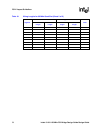
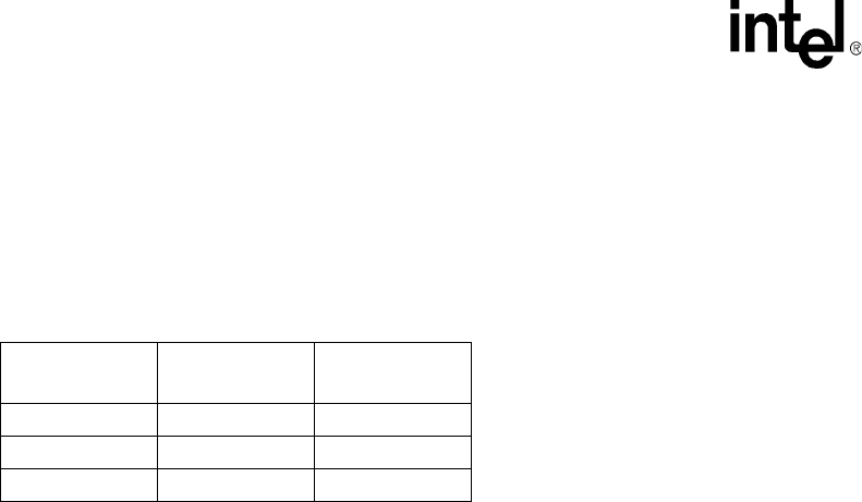
The PCI-X Addendum to the PCI Local Bus Specification, Revision 1.0a, recommends the
following guidelines for the number of loads for your PCI-X designs (Table 13). Any deviation
from these maximum values requires close attention to layout with regard to loading and trace
lengths.
The following PCI-X design layout considerations are compiled from the white paper Design,
Modeling and Simulation Methodology for High Frequency PCI-X Subsystems, available on the
http://www.pcisig.com website.
The following results are compiled from the simulation of system models that included system
board and add-in cards for different slot configurations and bus speeds (discussed in the white
paper mentioned above). This simulation addressed signal-integrity issues including reflective
noise, crosstalk noise, overshoot/undershoot voltage, ring-back voltage, settling time, inter-symbol
interference, input reference voltage offset, and ground-bounce effects. These results for the slot
configurations met the required PCI-X timing characteristics and were within appropriate noise
margins.
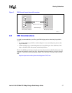
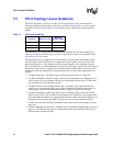
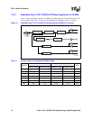
• 133 MHz Single-Slot—Included a single connection from the bridge to a single slot.
• 133 MHz Embedded—Included a single connection from the bridge to one additional device
on the system board. Note that this topology was interpolated from the above 133 MHz One-
Slot (not based on actual simulation results).
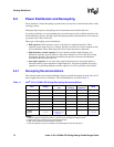
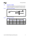
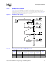
• 100 MHz Two-Slot Non-Hot-Plug, Balance Star—Included a single connection from the
bridge to two slots without hot-plug devices. The connections to the bridge and to each slot
came together such that each of the three branches is approximately the same length.
• 100 MHz Embedded Non-Hot-Plug, Balance Star—Included a single connection from the
bridge to three devices. The connections to the bridge and to each device came together such
that each of the three branches was approximately the same length. Note that this topology was
interpolated from the above 100 MHz Two-Slot (not based on actual simulation results).
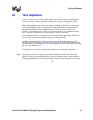
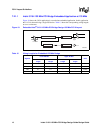
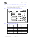
• 66 MHz Four-Slot Non-Hot-Plug—Included a single connection from the bridge to four hot-
plug slots.
• 66 MHz Embedded Non-Hot-Plug—Included a single connection from the bridge to four hot-
plug slots. Note that this topology was interpolated from the above 66 MHz Four-Slot (not
based on actual simulation results).
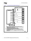
Table 13. PCI-X Slot Guidelines
Frequency Maximum Loads
Maximum
Number of Slots
66 MHz 8 4
100 MHz 4 2
133 MHz 2 1