


Intel
®
31154 133 MHz PCI Bridge Design Guide Design Guide 39
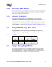
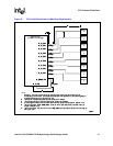
Routing Guidelines
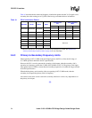
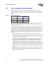
6.4 Trace Impedance
The PCI-X Addendum to the PCI Local Bus Specification, Revision 1.0b, recommends that all
signal layers have a controlled impedance of 57 Ω ±10% for add-in card applications. The
characteristic impedance of a signal trace is 60–100 Ω for PCI add-in card applications.
Selecting the appropriate board stack-up to minimize impedance variations is very important.
When calculating flight times, it is important to consider the minimum and maximum trace
impedance based on the switching neighboring traces. The PCI Local Bus Specification,
Revision 2.3, recommends a trace velocity of 150 ps/in to 190 ps/in. Use wider spaces between
traces, since this can minimize trace-to-trace coupling, and reduce crosstalk.
When a different stack-up is used, the trace widths must be adjusted appropriately. When wider
traces are used, the trace spacing must be adjusted accordingly (linearly).
It is highly recommended that a 2D field solver be used to design the high-speed traces. An
impedance calculator, available at http://emclab.umr.edu/pcbtlc, provides approximations for the
trace impedance of various topologies. These approximations may be used to generate the starting
point for a full 2D field solver.
The following website provides a useful basic guideline for calculating trace parameters:
http://www.ultracad.com/calc.htm
Note: Using stripline transmission lines may give better results than microstrip. This is due to the
difficulty of precisely controlling the dielectric constant of the solder mask, and the difficulty in
limiting the plated thickness of microstrip conductors, which can substantially increase crosstalk.
§ §