58 Intel
®
31154 133 MHz PCI Bridge Design Guide Design Guide
Power Considerations
8.2 Power Sequencing
When either P_VIO or S_VIO is connected to a power supply other than V
CCP
, you must perform
one of the following steps (listed in order from most favorably recommended to least favorably
recommended):
1. Ensure that the P_VIO or S_VIO power comes up before or simultaneously with V
CCP
, and
ensure that the P_VIO or S_VIO power goes down after or simultaneously with V
CCP
.
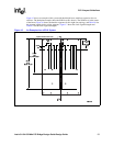
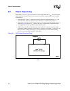
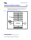
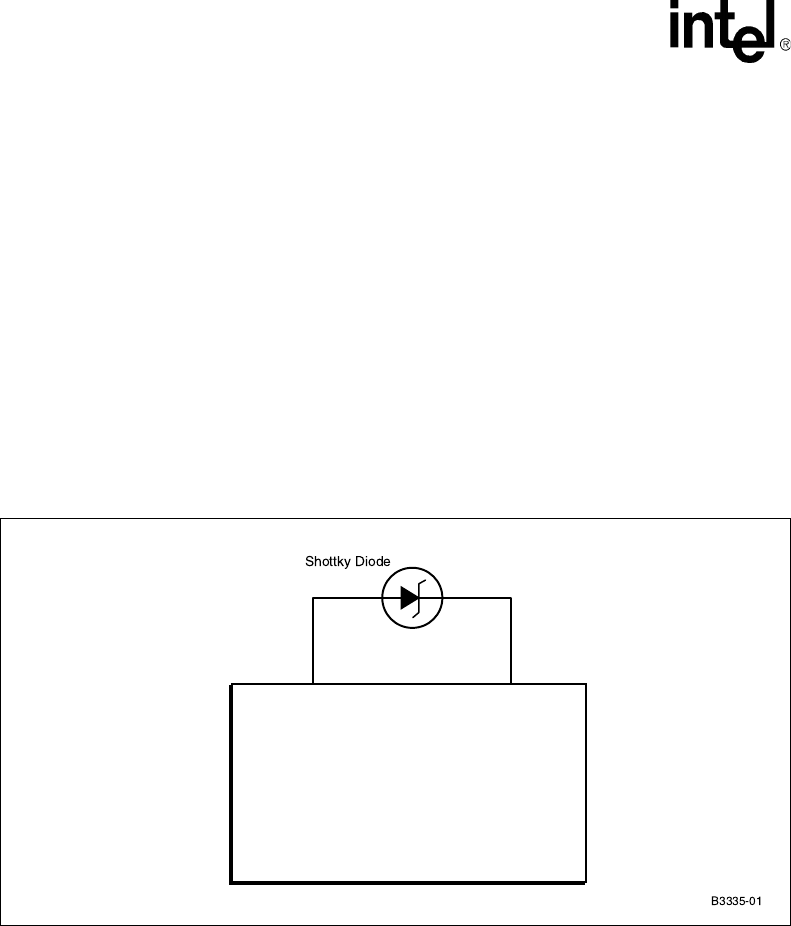
2. Alternatively, when the recommendation in item 1 is not followed, install a Schottky diode, as
shown in Figure 20, between V
CCP
and the VIO pin(s) (as appropriate). The diode must be
sized appropriately for the power environment of the system.
3. Alternatively, when the recommendations in item 1 and item 2 are not followed, connect a
25 Ω current-limiting resistor in series with the P_VIO and S_VIO supply. P_VIO and S_VIO
must never be at a voltage lower than V
CCP
except in the case of a 25 Ω current-limiting
resistor in series with the P_VIO and S_VIO supply.
§ §
Figure 20. PVIO Voltage Protection Diode
Intel
®
31154
133 MHz PCI Bridge
VCP VIO


