


24 Intel
®
31154 133 MHz PCI Bridge Design Guide Design Guide
Terminations
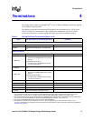
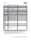
OPAQUE_EN
To enable Opaque Memory Base/Limit Registers
to establish a private memory space for secondary
bus usage:
• Pull high to 3.3 V through an external 8.2 KΩ
resistor.
To disable Opaque Memory Base/Limit Registers:
• Pull low to GND through an external 220 Ω
resistor (default).
IDSEL_MASK
To enable device hiding after reset (in other words,
to hide device numbers 16–21 from the host):
• Pull high to 3.3 V through an external resistor.
To disable device hiding after reset:
• Pull low to GND through an external 220 Ω
resistor (default).
After reset, device hiding can be performed
through software through the Secondary IDSEL
Select Register (Offset 5Ch).
DEV_64BIT#
This bit is used by the system management
software to help the user identify the best slot for
an add-in card:
• When the 31154 is installed on an add-in card
and the add-in card implements a 64-bit PCI
connector, pull up to 3.3 V through an external
8.2 KΩ resistor.
• When the 31154 is not installed on an add-in
card or the add-in card implements only a
32-bit PCI connector, pull low to GND through
a 220 Ω external resistor (default).
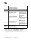
Serial EEPROM
SR_CLK
Serial ROM clock input:
• Connect to the clock input of the EEPROM.
• NC when EEPROM is not required in design.
SR_DI
Serial ROM data input:
• Connect to the DI input of the EEPROM.
• NC when EEPROM is not required in design.
SR_DO
Serial ROM data output:
• Connect to the DO output of the EEPROM.
• Tie high or pull to GND when EEPROM is not
required in design.
NOTE: When EEPROM is present but register
preload is not desired, bits[7:6] of the first
byte can be any value except the preload
enable value (10b).
SR_CS
Serial ROM chip select:
• Connect to the chip select of the EEPROM.
• NC when EEPROM is not required in design.
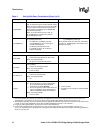
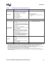
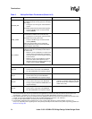
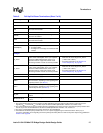
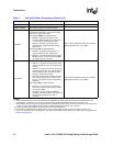
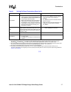
Table 5. Pull-Up/Pull-Down Terminations (Sheet 6 of 9)
Signal Pull-Up/Pull-Down or Termination (See Note 1) Comments
NOTES:
1. The recommended value for pull-up resistors for PCI applications is 5.6 KΩ (note that the minimum value for PCI 3.3 V
signaling R
MIN
=2.42KΩ, R
TYP
=8.2KΩ, as per the PCI Local Bus Specification, Revision 2.3, section 4.3.3).
2. The recommended value for pull-up resistors for PCI-X applications is 8.2 KΩ. For PCI-X, the minimum pull-up resistor value
is 5 KΩ, as per the PCI-X Addendum to the PCI Local Bus Specification, Revision 1.0b, section 9.7.
3. For plug-in card implementations, the pull-up must be on the motherboard.
4. Connect PVIO and SVIO pull-up resistors to 5 V or 3.3 V power supply through an external resistor—25 Ω (5 V) or
0 Ω (3.3 V), depending on the signaling level of the primary/secondary PCI bus. Refer to the power-sequencing guidelines in
Section 8.2 on page 58
.