


Intel
®
31154 133 MHz PCI Bridge Design Guide Design Guide 21
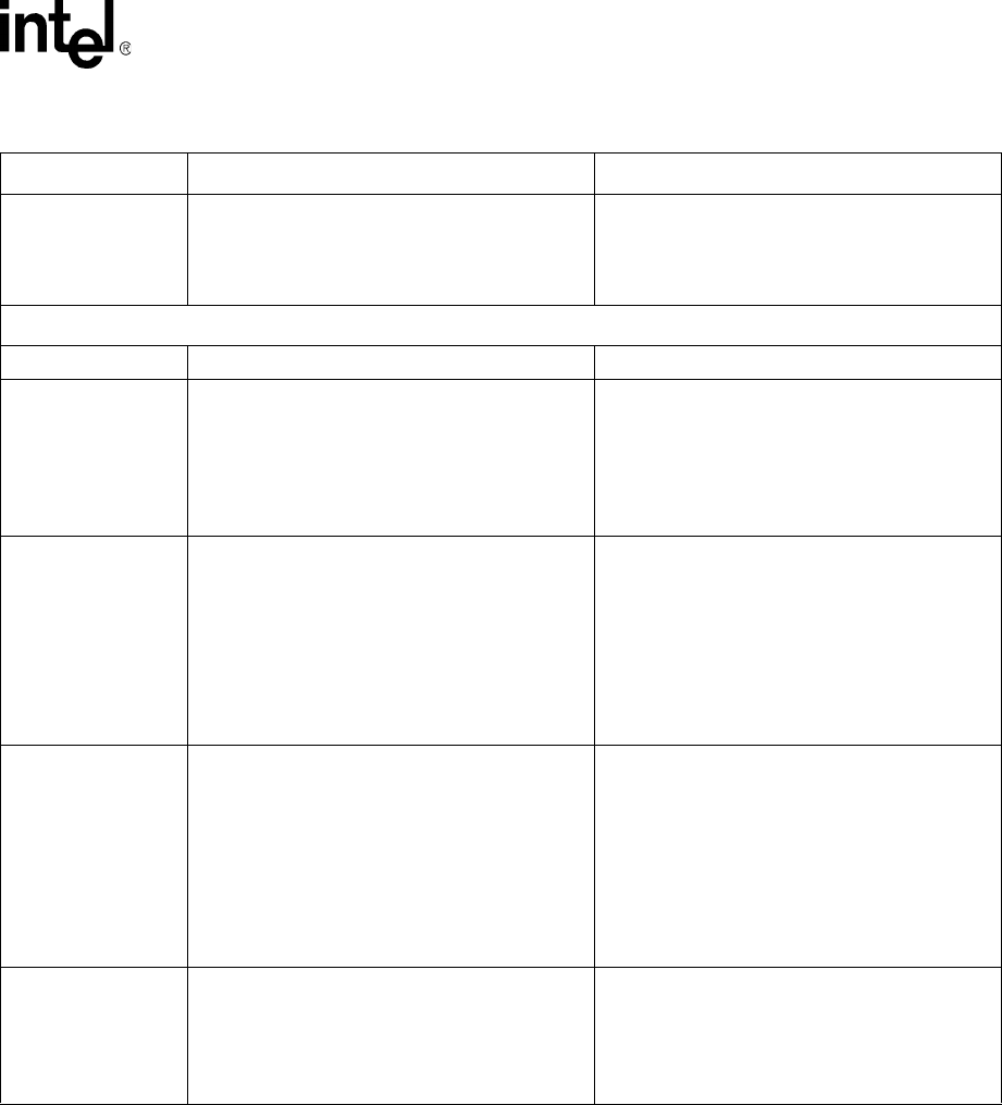
Terminations
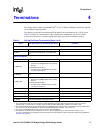
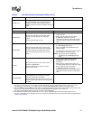
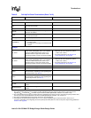
S_AD[31:17]
These signals can be used as IDSEL lines and are
connected to IDSEL of the secondary PCI bus
through an external series coupling resistor (a
resistor of 2 KΩ is used on the customer reference
board).
PCI Clocks
P_CLK Connect to the PCI clock on the primary PCI bus.
S_BRGCLKO
When the internal clock of the 31154 is used,
connect to S_CLKI through a 33.2 Ω series
resistor.
NC when external clock is used.
• All S_CLKO[8:0] and S_BRGCLKO must
match in length.
• When there are PCI slots in the design,
S_BRGCLKO must be 3" longer to
compensate for the 2.5" trace length from the
connector to the PCI device on a PCI add-in
card.
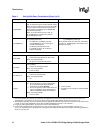
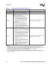
S_CLKO[8:0]
When the internal clock of the 31154 is used,
connect to the PCI clock input of the secondary
PCI devices through a 33.2 Ω series resistor.
Each clock can be connected to only one PCI
device.
• These clocks can be disabled by strapping the
S_CLKOEN[3:0] during reset.
• All S_CLKO[8:0] and S_BRGCLKO must
match in length.
• For asynchronous mode, there is no maximum
skew between P_CLK and S_CLKI.
NOTE: These clocks can be disabled by
strapping the S_CLKOEN[3:0] during
reset.
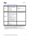
S_CLKI
When the internal clock of the 31154 is used,
connect to S_BRGCLKO.
When an external clock is used, connect to
external clock source.
• When using the internal clock, refer to
S_BRGCLKO (above) for additional
information.
• When using an external clock source, all
secondary clocks must have matching length.
• When using PCI slots in the design,
S_BRGCLKO must be 3" longer to
compensate for the 2.5" trace length from the
connector to the PCI device on a PCI add-in
card.
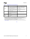
S_CLKSTABLE
When the internal clock of the 31154 is used,
S_CLKSTABLE must be tied high to VCC33
through an external 8.2 KΩ resistor.
When an external clock source is used, connect to
logic that outputs high after the secondary clocks
are stable.
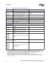
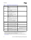
Table 5. Pull-Up/Pull-Down Terminations (Sheet 3 of 9)
Signal Pull-Up/Pull-Down or Termination (See Note 1) Comments
NOTES:
1. The recommended value for pull-up resistors for PCI applications is 5.6 KΩ (note that the minimum value for PCI 3.3 V
signaling R
MIN
= 2.42 KΩ, R
TYP
=8.2KΩ, as per the PCI Local Bus Specification, Revision 2.3, section 4.3.3).
2. The recommended value for pull-up resistors for PCI-X applications is 8.2 KΩ. For PCI-X, the minimum pull-up resistor value
is 5 KΩ, as per the PCI-X Addendum to the PCI Local Bus Specification, Revision 1.0b, section 9.7.
3. For plug-in card implementations, the pull-up must be on the motherboard.
4. Connect PVIO and SVIO pull-up resistors to 5 V or 3.3 V power supply through an external resistor—25 Ω (5 V) or
0 Ω (3.3 V), depending on the signaling level of the primary/secondary PCI bus. Refer to the power-sequencing guidelines in
Section 8.2 on page 58
.