


Intel
®
31154 133 MHz PCI Bridge Design Guide Design Guide 45
PCI-X Layout Guidelines
7.2.1 Single Slot at 133 MHz
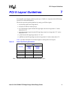
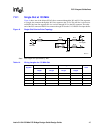
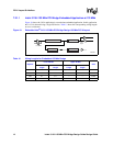
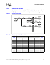
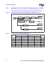
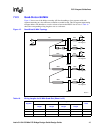
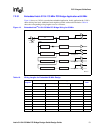
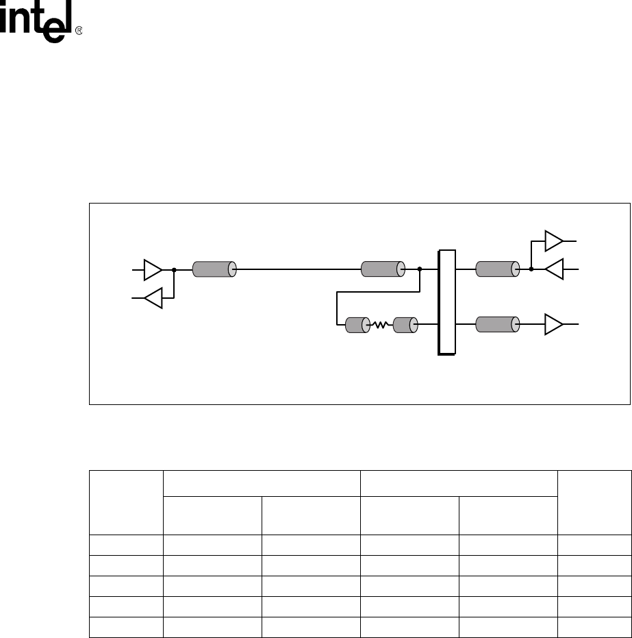
Figure 9 shows one of the chipset PCI AD lines connected through the W1 and W12 line segments
to a single-slot connector through the W13 line segment to the 31154. This AD line is also used as
an IDSEL line from line segment W14 to a resistor through W15 to the PCI connector. The other
end of the PCI connector IDSEL line connects through W16 to the 31154 IDSEL line input buffer.
Note: Stub lengths are represented by W#s.
Figure 9. Single-Slot Point-to-Point Topology
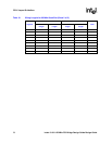
Table 14. Wiring Lengths for 133 MHz Slot
Segment
Lower AD Bus Upper AD Bus
Units
Minimum
Length
Maximum
Length
Minimum
Length
Maximum
Length
W1 + W12 5.5 10.5 4.5 9.5 inches
W13 0.75 1.5 1.75 2.75 inches
W140.1 0.1 – –inches
W150.6 0.6 – –inches
W16 1.125 1.125 – – inches
B3057-01
W1 W12
W14 W15
W16
W13
I/O Buffer
Slot 1
PCI Agent 1
PCI Connector