38 Intel
®
31154 133 MHz PCI Bridge Design Guide Design Guide
Routing Guidelines
6.3 Power Distribution and Decoupling
Ensure that there is ample decoupling to ground for the power planes, to minimize the effects of the
switching currents.
Inadequate high-frequency decoupling results in intermittent and unreliable behavior.
As a general guideline, it is recommended that you use the largest easily available capacitor in the
lowest-inductance package. The high-speed decoupling capacitor must be placed as close to the pin
as possible, with a short, wide trace.
Three types of decoupling are described below:
• Bulk capacitor: Bulk capacitors consist of electrolytic or tantalum capacitors. These
capacitors supply large reservoirs of charge, but they are useful only at lower frequencies due
to lead-inductance effects. Bulk capacitors can be located anywhere on the board.
• High-frequency ceramic capacitor: For fast switching currents, high-frequency low-
inductance capacitors are most effective. Place these capacitors as close to the device being
decoupled as possible. This placement minimizes the parasitic resistance and inductance
associated with board traces and vias.
• Inter-plane capacitor: Use an inter-plane capacitor between power and ground planes to
reduce the effective plane impedance at high frequencies. The general guideline for placing
capacitors is to place high-frequency ceramic capacitors as close as possible to the module.
6.3.1 Decoupling Recommendations
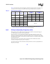
This section describes the recommended high-frequency and bulk decoupling for each of the 31154
power supplies based on our simulations. The recommendations are listed in Table 11.
Table 11. Intel
®
31154 133 MHz PCI Bridge Decoupling Recommendations
Pins Voltage
Capacitor Value
(µF)
Capacitor
Package
Number of
Capacitors
Notes
VCC33 3.3 V 22 1210 3 2, 3, 4
VCC33 3.3 V 0.1 603 12 2, 3, 4
VCC33 3.3 V 150 7343 1 2, 3, 4
VCC 1.3 V 22 1210 3 2, 3, 4
VCC 1.3 V 0.1 603 12 2, 3, 4
P_VIO, S_VIO 3.3 V/5.0 V 22 1210 1 2, 3, 4
P_VIO, S_VIO 3.3 V/5.0 V 0.1 603 4 2, 3, 4
P_VCCA,
S_VCCA
1.3 V
Refer to
Section 8.1 on
page 57.
––1, 2, 3, 4
NOTES:
1. Separate capacitor required only when P_VIO and S_VIO are not connected to VCC33.
2. Polymerized organic capacitors are recommended for bulk.
3. X5R, X7R, or COG are recommended for ceramics.
4. Place all capacitors as close as possible to associated pins to minimize inductance.


