Intel
®
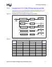
31154 133 MHz PCI Bridge Design Guide Design Guide 23
Terminations
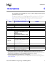
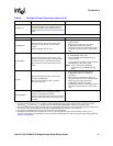
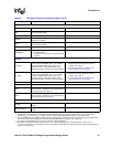
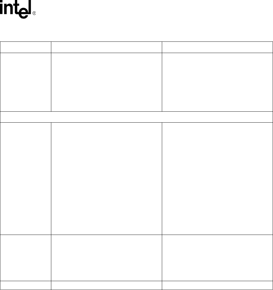
HS_FREQ[1:0]
For Hot Swap:
• Depending on Primary PCI Bus frequency
00 = PCI Mode, 33 or 66 MHz (default)
01 = PCI-X 66 MHz
10 = PCI-X 100 MHz
11 = PCI-X 133 MHz
When not using Hot Swap:
• Tie low to GND.
Only valid when HS_SM = 1.
0 = Tie low to GND.
1 = Pull high to 3.3 V through external 8.2 KΩ
resistor.
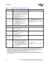
Hardware Straps (sampled at the edge of P_RST#)
S_ARB_DISABLE/
S_ARB_LOCK
To disable internal secondary arbiter:
• Pull up to 3.3 V through an external 8.2 KΩ
resistor.
• S_GNT0# becomes the secondary PCI bus
request output of the 31154, and S_REQ0#
becomes the secondary PCI bus grant input of
the 31154.
To enable internal secondary arbiter:
• Pull down to GND through an external 220 Ω
resistor (default).
S_ARB_LOCK (after trailing edge of P_RST#):
• Sampled as 1b, the internal secondary bus
arbiter of the 31154 locks and provides the
grant only to itself.
• When internal arbiter is used and 1b is
sampled after the trailing edge of P_RST#, the
internal secondary bus arbiter of the 31154
locks and provide grant only to itself.
NOTE: S_ARB_LOCK has an effect only when
the internal arbiter is enabled.
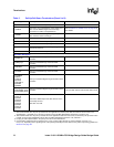
S_MAX100
To limit secondary bus frequency to maximum of
100 MHz:
• Pull high to 3.3 V through an external 8.2 KΩ
resistor.
Otherwise:
• Pull low to GND through an external 330 Ω
resistor (default).
S_TRISTATE GND during normal operation
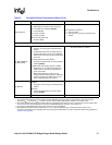
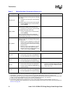
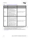
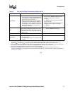
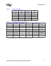
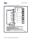
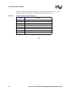
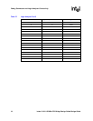
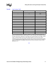
Table 5. Pull-Up/Pull-Down Terminations (Sheet 5 of 9)
Signal Pull-Up/Pull-Down or Termination (See Note 1) Comments
NOTES:
1. The recommended value for pull-up resistors for PCI applications is 5.6 KΩ (note that the minimum value for PCI 3.3 V
signaling R
MIN
= 2.42 KΩ, R
TYP
=8.2KΩ, as per the PCI Local Bus Specification, Revision 2.3, section 4.3.3).
2. The recommended value for pull-up resistors for PCI-X applications is 8.2 KΩ. For PCI-X, the minimum pull-up resistor value
is 5 KΩ, as per the PCI-X Addendum to the PCI Local Bus Specification, Revision 1.0b, section 9.7.
3. For plug-in card implementations, the pull-up must be on the motherboard.
4. Connect PVIO and SVIO pull-up resistors to 5 V or 3.3 V power supply through an external resistor—25 Ω (5 V) or
0 Ω (3.3 V), depending on the signaling level of the primary/secondary PCI bus. Refer to the power-sequencing guidelines in
Section 8.2 on page 58
.