


Intel
®
31154 133 MHz PCI Bridge Design Guide Design Guide 53
PCI-X Layout Guidelines
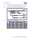
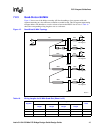
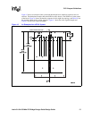
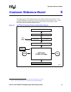
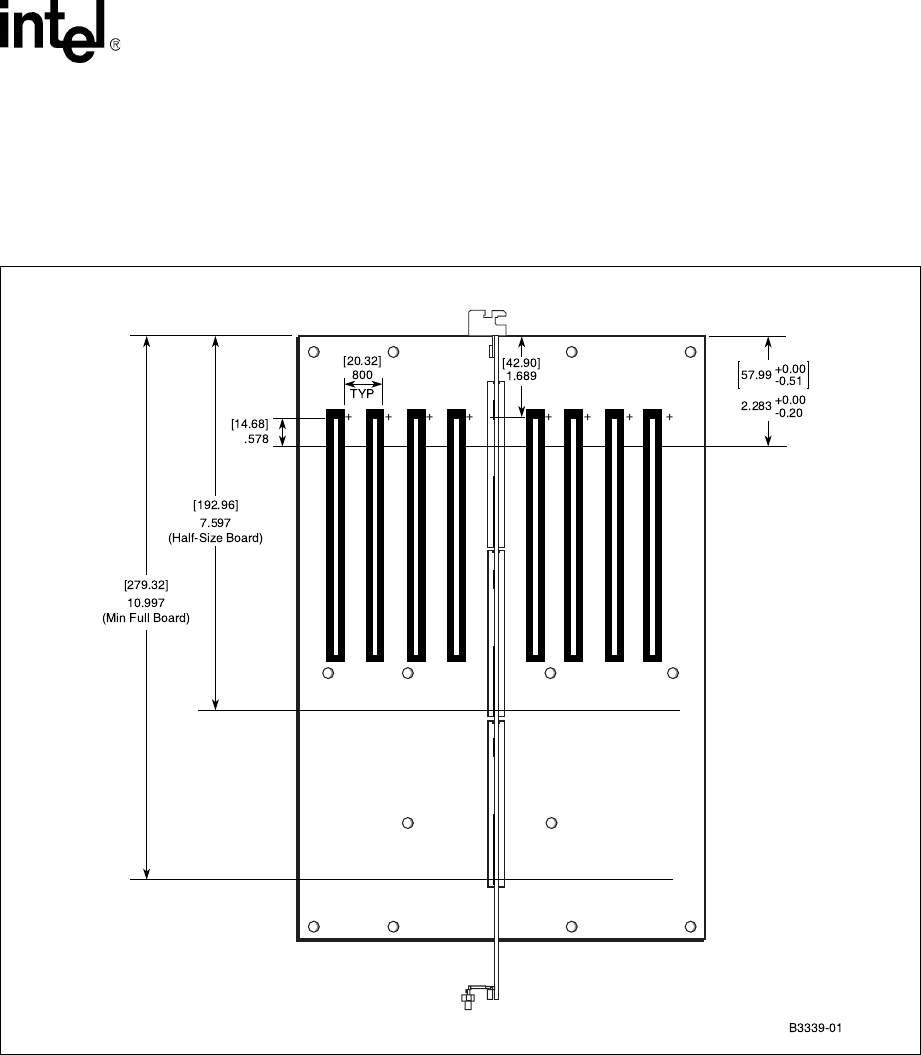
Figure 15 shows an example of this system with dual 64-bit buses with four expansion slots on
each bus. The backplane example shows the SHB in an ISA chassis. The SHB slot is in the center
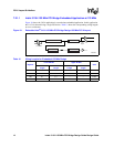
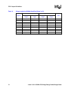
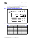
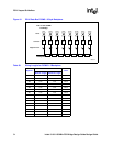
of the board. Figure 16 shows the data bus segments for this eight-slot topology, and Table 20 lists
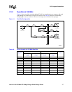
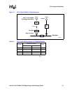
the segment lengths for the wiring segments. Figure 17 shows the clock segment lengths and
Table 21 lists the clock segments lengths.
Figure 15. An Example of an ePCI-X System
Option Bracket Front Plate