


22 Intel
®
31154 133 MHz PCI Bridge Design Guide Design Guide
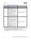
Terminations
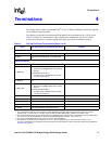
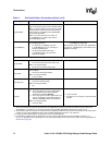
S_GCLKOEN
When the internal clock of the 31154 is used, pull
high to VCC33 through an external 8.2 KΩ resistor.
When an external clock source is used, tie to GND
through a 330 Ω external resistor. All secondary
clock outputs (S_CLKO[8:0] and S_BRGCLKO)
asynchronously tristate.
When an external clock source is used, tie
S_CLKOEN[3:0] to a stable value. Refer to
S_CLKOEN[3:0], below.
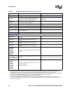
S_CLKOEN[3:0]
These are strapping pins to enable or tristate
S_CLKO[8:0] after reset.
• To enable all S_CLKO[8:0], pull each
S_CLKOEN[3:0] pin to 3.3 V through an
external 8.2 KΩ resistor.
• To selectively disable some of the
S_CLKO[8:0], refer to 31154 Control
Register 2, bits[8:0].
NOTE: This strapping is meaningful only when
S_GCLKOEN is pulled high.
When external clocks are used, tie S_GCLKOEN
low and tie S_CLKOEN[3:0] to some stable value
(0000b, for example).
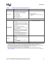
Hot Swap
HS_ENUM#
For Hot Swap:
• Connect the interrupt input pin to the host.
When not using Hot Swap:
• NC (there is a weak internal pull-up).
HS_LSTAT
For Hot Swap:
• Connect to cPCI ejector switch.
When not using Hot Swap:
• Tie low to GND.
HS_LED_OUT
For Hot Swap:
• Connect to cPCI blue LED.
When not using Hot Swap:
•NC
HS_SM
For Hot Swap:
0 = The 31154 retries any Type 0 configuration
cycles addressed to it until serial ROM
preload has completed (default)
1 = The 31154 ignores (causes master abort) any
Type 0 configuration cycles addressed to it
until its serial ROM preload has completed.
When not using Hot Swap:
• Tie low to GND.
0 = Tie low to GND.
1 = Pull high to 3.3 V through an external 8.2 KΩ
resistor.
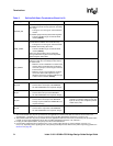
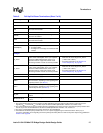
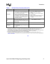
Table 5. Pull-Up/Pull-Down Terminations (Sheet 4 of 9)
Signal Pull-Up/Pull-Down or Termination (See Note 1) Comments
NOTES:
1. The recommended value for pull-up resistors for PCI applications is 5.6 KΩ (note that the minimum value for PCI 3.3 V
signaling R
MIN
=2.42KΩ, R
TYP
=8.2KΩ, as per the PCI Local Bus Specification, Revision 2.3, section 4.3.3).
2. The recommended value for pull-up resistors for PCI-X applications is 8.2 KΩ. For PCI-X, the minimum pull-up resistor value
is 5 KΩ, as per the PCI-X Addendum to the PCI Local Bus Specification, Revision 1.0b, section 9.7.
3. For plug-in card implementations, the pull-up must be on the motherboard.
4. Connect PVIO and SVIO pull-up resistors to 5 V or 3.3 V power supply through an external resistor—25 Ω (5 V) or
0 Ω (3.3 V), depending on the signaling level of the primary/secondary PCI bus. Refer to the power-sequencing guidelines in
Section 8.2 on page 58
.