


26 Intel
®
31154 133 MHz PCI Bridge Design Guide Design Guide
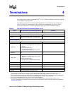
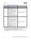
Terminations
RSTV0 Tie to GND through a 0 Ω external resistor.
RSRV1/CRSTEN Tie to GND through a 0 Ω external resistor.
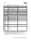
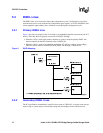
S_M66EN
S_M66EN is meaningful only when S_PCIXCAP is
connected to GND (that is, when the secondary
PCI bus is in legacy PCI mode).
For designs without secondary PCI slot:
• When the secondary PCI devices (and
loading) support 66 MHz PCI bus, pull up to
3.3 V through an 8.2 KΩ series resistor.
• When the secondary PCI devices (and
loading) do not supports 66 MHz PCI bus,
GND this pin.
For designs with secondary PCI slot:
• When the on-board PCI device does not
support 66 MHz PCI bus, GND this pin.
• When the on-board PCI device does support
66 MHz PCI bus, connect this pin to M66EN
(pin 49B) of the PCI connector.
Refer to PCI-X Addendum to the PCI Local Bus
Specification, Revision 1.0b, Table 6-1.
S_PCIXCAP
For designs without secondary PCI slot:
• When there is at least one legacy PCI device
on the secondary PCI bus, tie this pin directly
to GND.
• When there is at least one PCI-X device that
supports maximum PCI-X of only 66 MHz on
the secondary PCI bus, pull down to GND
through a 10 KΩ series resistor.
• When all secondary PCI-X devices (and the
bus loading) support PCI-X 133 MHz, leave
this pin unconnected (except for decoupling
capacitor).
For designs with secondary PCI slot:
• When there is at least one on-board legacy
PCI device on the secondary PCI bus, tie this
pin directly to GND.
• Otherwise, connect this pin to PCIXCAP
(pin B38) of the PCI connector (assuming that
the bus loading supports up to PCI-X
133 MHz)
Refer to PCI-X Addendum to the PCI Local Bus
Specification, Revision 1.0b, Table 6-1.
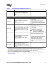
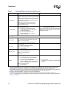
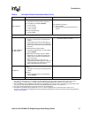
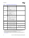
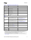
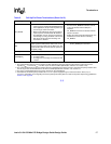
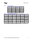
Table 5. Pull-Up/Pull-Down Terminations (Sheet 8 of 9)
Signal Pull-Up/Pull-Down or Termination (See Note 1) Comments
NOTES:
1. The recommended value for pull-up resistors for PCI applications is 5.6 KΩ (note that the minimum value for PCI 3.3 V
signaling R
MIN
=2.42KΩ, R
TYP
=8.2KΩ, as per the PCI Local Bus Specification, Revision 2.3, section 4.3.3).
2. The recommended value for pull-up resistors for PCI-X applications is 8.2 KΩ. For PCI-X, the minimum pull-up resistor value
is 5 KΩ, as per the PCI-X Addendum to the PCI Local Bus Specification, Revision 1.0b, section 9.7.
3. For plug-in card implementations, the pull-up must be on the motherboard.
4. Connect PVIO and SVIO pull-up resistors to 5 V or 3.3 V power supply through an external resistor—25 Ω (5 V) or
0 Ω (3.3 V), depending on the signaling level of the primary/secondary PCI bus. Refer to the power-sequencing guidelines in
Section 8.2 on page 58
.