Intel
®
41210 Serial to Parallel PCI Bridge Developer’s Manual 15
Signal Description
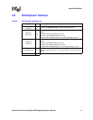
2.2 PCI Express* Interface
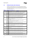
Table 2. PCI Express* Interface Pins
Signal I/O Description
REFCLKp/
REFCLKn
I PCI Express* Reference Clocks: 100 MHz differential clock pair
PETp[7:0]/
PETn[7:0]
O
PCI Express* Serial Data Transmit: PCI Express* differential data transmit
signals
X8 Mode: All PETp[7:0]/PETn[7:0] are used.
X4 Mode: Only PETp[3:0]/PETn[3:0] are used.
X1 Mode: Either PETp[0]/PETn[0] is used or PETp[7]/PETn[7] is used.
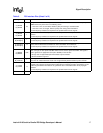
PERp[7:0]/
PERn[7:0]
I
PCI Express* Serial Data Receive: PCI Express* differential data receive
signals
X8 Mode: All PERp[7:0]/PERn[7:0] are used.
X4 Mode: Only PERp[3:0]/PERn[3:0] are used.
X1 Mode: Either PERp[0]/PERn[0] is used or PERp[7]/PERn[7] is used.
PE_RCOMP[1:0] I
PCI Express* Compensation Inputs: Analog signals. Connect to a
24.9 Ω ±1% pull-up resistor to 1.5 V. A single resistor can be used for both
signals.
Total 36


