96 Intel
®
41210 Serial to Parallel PCI Bridge Developer’s Manual
Register Description
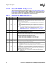
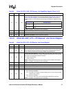
12.2.32 Offset 56h: EXP_LSTS—PCI Express* Link Status Register
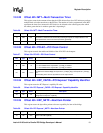
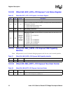
12.2.33 Offset 5Ch: MSI_CAPID—PCI Express* MSI Capability
Identifier
Note: MSI generation is used for internal debugging purposes and does not occur in normal operation.
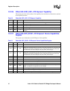
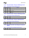
12.2.34 Offset 5Dh: MSI_NXTP—PCI Express* Next Item Pointer
Table 66. Offset 56h: EXP_LSTS—PCI Express* Link Status Register
Bits Type Default Description
15:13 RsvdZ 000b Reserved Zero: Software must always write 0 to these bits.
12 RO 1b
Slot Clock Configuration: When the Intel
®
41210 Serial to Parallel PCI Bridge is on a PCI
Express* connector, this bit indicates whether it is using the same reference clock that is
provided at the connector.
0 = Indicates independent reference clock
1 = Indicates same reference clock.
11 RO 0b
Link Training: Not applicable
10 RO 0b
Link Width Negotiation Error: Not applicable
9:4 RO
Set by PCI
Express*
Link Layer
after
training is
complete
Negotiated Link Width: This field indicates the negotiated width of the PCI Express* link.
• 00 0001b X1
• 00 0010b X2—not supported
• 00 0100b X4
• 00 1000b X8
• 00 1100b X12—not supported
• 01 0000b X16—not supported
• 10 0000b X32—not supported
• All other values are reserved.
3:0 RO 1h
Link Speed: The only speed supported is 2.5 Gbps.
Table 67. Offset 5Ch: MSI_CAPID—PCI Express* MSI Capability Identifier
Bits Type Reset Description
7:0 RO 05h Capability ID (MCID): Capabilities ID indicates MSI.
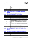
Table 68. Offset 5Dh: MSI_NXTP—PCI Express* Next Item Pointer
Bits Type Reset Description
7:0 RO 6Ch
Next Pointer (MNPTR): This field points to the next capabilities list pointer, which is the PCI
Express* Power Management capability item.


