


36 Intel
®
41210 Serial to Parallel PCI Bridge Developer’s Manual
PCI-X Interface
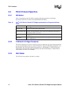
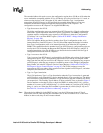
For controlling the priority level, there is one bit for each of the PCI REQ# inputs and one bit for the
internal request input. Bit[7] in the control register is for the bridge, bit[5] is for REQ[5]#, bit[4] is for
REQ[4]#, and so on. A value of 1 in a bit position puts the corresponding master in the high-priority
group.
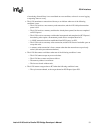
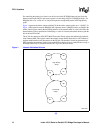
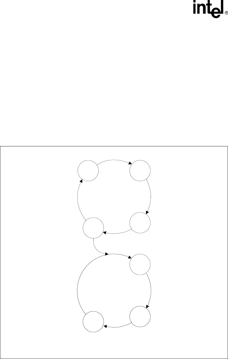
Figure 1 represents the arbiter scheme with bits[7:0] in the arbiter control register set to “110 0011”. In
Figure 1, M0 represents master 0 (REQ[0]#), M1 represents master 1 (REQ[1]#) and so on. Bit[8] in the
arbiter control register controls the bus parking behavior of the internal arbiter. A value of 0 instructs the
internal arbiter to always park the bus on the bridge. A value of 1 instructs the internal arbiter to park the
bus on the last PCI master.
The 41210 also supports an 8-bit MTT (Multi-Transaction Timer) register that influences the behavior
of the internal arbiter. This register controls the amount of time that the arbiter allows a PCI initiator to
perform multiple back-to-back transactions on the PCI bus. The number of clocks programmed in the
MTT represents the minimum length of time on the PCI bus that the master is granted the bus as long as
the REQ of that master is asserted, before the GNT is given to the next master.
§ §
Figure 1. Internal Arbitration Scheme
B3173-01
M0
M1
lpg
Bridge
M2
M3
M4
High Priority
Group
Low Priority
Group