Intel
®
41210 Serial to Parallel PCI Bridge Developer’s Manual 95
Register Description
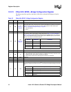
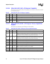
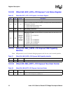
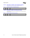
12.2.31 Offset 54h: EXP_LCTL—PCI Express* Link Control Register
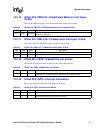
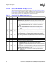
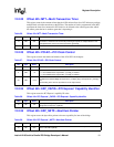
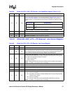
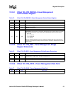
14:12 RO 110b
L0s Exit Latency: The value in these bits is determined by the setting of the Common
Clock Configuration bit (bit[6]) in the Link Control Register (Offset 54h: EXP_LCTL—PCI
Express* Link Control Register). Note that software can write bit[6] in the Link Control
Register to either a 1 or 0 and these bits then change accordingly. The mapping is shown
below:
NOTE: L0s ASPM is not supported in the 41210 Bridge.
11:10 RO 01b L0s ASPM is not supported in the 41210 Bridge.
9:4 RO 08h
Maximum Link Width: X8 link width is supported.
3:0 RO 1h
Maximum Link Speed: 2.5 Gb/s link speed is supported.
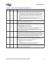
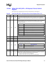
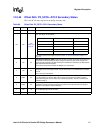
Table 65. Offset 54h: EXP_LCTL—PCI Express* Link Control Register
Bits Type Default Description
15:8 RsvdP 00h Preserved
7RW 0b
Extended Synch.: When set, this bit forces extended transmission of 4096 FTS ordered
sets in FTS and an extra 1024 TS1 at exit from L1 prior to entering L0. This mode provides
external devices monitoring the link time to achieve bit and symbol lock before the link
enters L0 state and resumes communication. Default value for this bit is 0.
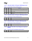
6RW 0b
Common Clock Configuration: This bit indicates the relationship of the reference clock
between the Intel
®
41210 Serial to Parallel PCI Bridge and the component at the opposite
end of the 41210 Upstream PCI Express* interface:
0 = Clock is asynchronous.
1 = Clock is common.
NOTE: This bit determines the proper L0s exit latency value in the EXP_LSTS register.
NOTE: L0s ASPM is not supported in the 41210 Bridge.
5RO 0b
Retrain Link: Not applicable
4RO 0b
Disable Link: Not applicable
3RO 0b
Read Completion Boundary Control: Not used
2 RsvdP 0b Preserved
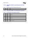
1:0 RW 00b
ASPM Control: Enables bridge upstream interface to enter L0s:
• 00b = L0s entry is disabled.
• 01b = The Intel
®
41210 Serial to Parallel PCI Bridge enters L0s as per the specification
requirement for L0s entry.
• 10b = L0s entry is disabled.
• 11b = The 41210 enters L0s as per the specification requirement for L0s entry.
NOTE: L0s ASPM is not supported in the 41210 Bridge.
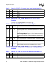
Table 64. Offset 50h: EXP_LCAP—PCI Express* Link Capabilities Register (Sheet 2 of 2)
Bits Type Default Description
Bit 6 in LCTL L0s Exit Latency
0
110b (because currently L0s cannot work with different reference
clocks)
1 010b


