Intel
®
41210 Serial to Parallel PCI Bridge Developer’s Manual 99
Register Description
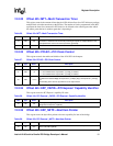
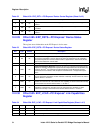
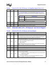
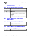
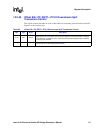
12.2.41 Offset 70h: PM_PMCSR—Power Management
Control/Status Register
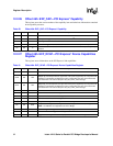
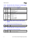
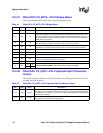
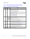
12.2.42 Offset 72h: PM_BSE—Power Management Bridge
Support Extensions
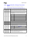
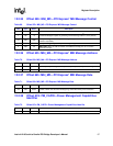
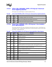
12.2.43 Offset 73h: PM_DATA—Power Management Data Field
Table 75. Offset 70h: PM_PMCSR—Power Management Control/Status Register
Bits Type Reset Description
15 RO 0b PME Status: Not supported
14:13 RO 00h
Data Scale: Not supported
12:9 RO 0h
Data Select: Not supported
8RWS 0b
PME En: Not supported
7:2 RsvdP 00 0000b Preserved
1:0 RW 00b
Power State: This 2-bit field is used both to determine the current power state of a function
and to set the function into a new power state. Supported field values are given below.
• 00b = D0
• 01b = Reserved
• 10b = Reserved
• 11b = D3 hot
When the software attempts to write an unsupported, optional state to this field, the write
operation must complete normally on the bus; however, the data is discarded and no state
change occurs.
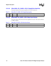
Table 76. Offset 72h: PM_BSE—Power Management Bridge Support Extensions
Bits Type Reset Description
7RO 0b
BPCC_En (Bus Power/Clock Control Enable): Neither bus or clock control of PCI is
supported when in D3hot state. This bit is hard-wired to 0.
6RO 0b
B2/B3#: Not supported. This bit has no meaning since the BPCC_En bit is hard-wired to 0.
5:0 RsvdP 00h Preserved
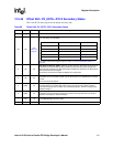
Table 77. Offset 73h: PM_DATA—Power Management Data Field
Bits Type Reset Description
7:0 RO 00h Data: Not supported


