Intel
®
440GX AGPset Design Guide
2-9
Motherboard Layout and Routing Guidelines
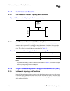
In the SET topology, the only termination is on the Intel
®
Pentium
®
II processor substrate. There is
no termination present at the other end of the network. Due to the lack of termination, SET exhibits
much more ringback than the dual terminated topology. Extra care is required in SET simulations
to make sure that the ringback specs are met under the worst case signal quality conditions.
In addition, since there is only one pull-up resistor per net the rising edge response is substantially
degraded when using slow corner buffers. This effect manifests itself as a degraded flight time,
which results in a reduced maximum trace length that meets the 100 MHz timing requirements.
This loss of design flexibility must be carefully weighed against the cost savings from removing
the resistors.
2.3.5.2 SET Trace Length Requirements
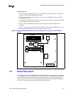
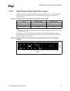
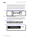
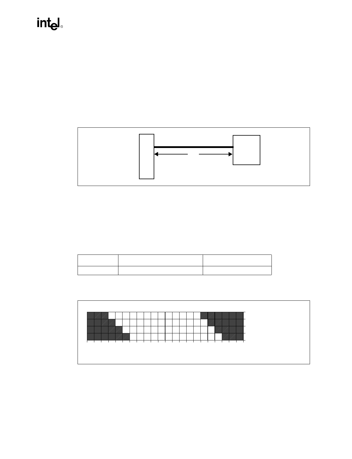
Intel has performed sensitivity analysis on the SET topology. The required trace lengths for
operation at 100 MHz with the SET topology are based on the sensitivity analysis results, and are
listed in Table 2-3. Intel’s SET simulations were performed assuming a four layer system board, so
that all traces used the microstrip propagation velocity range. The slower propagation of stripline
transmission line structures is not included in the recommendations of Table 2-3.
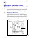
Figure 2-10. Topology for Single Processor Designs With Single-End Termination (SET)
Slot 1
Intel
®
440GX
AGPset
L1
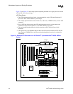
Table 2-3. SET Trace Length Requirements
Trace Minimum Length Maximum Length
L1 1.50” 4.00”
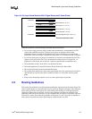
Figure 2-11. Solution Space for Single Processor Designs With Single-End Termination (SET)
0.0 1.0 2.0 3.0 4.0 5.0
1.5
2.0
2.5
L1 [in]
SUBSTRATE
TRACE LENGTH
[IN]


