Intel
®
440GX AGPset Design Guide
2-33
Motherboard Layout and Routing Guidelines
2.9.6.3 PCI Clock Layout
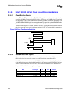
PCI clock nets should be routed a point-to-point connections with a 22 Ohm series resistor that is to
be placed as close to the output pins on the clock driver as possible (<0.5”). Layout guidelines:
Match trace lengths to the longest trace.
2.9.6.4 SDRAM Clock Layout
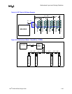
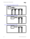
Series Termination: No series termination is required for the SDRAM clocks between the CKBF
and the DIMMs. For DCLKO (between 82443GX and CKBF), two termination resistors are
required: A 22 Ohm series resistor located at the driver, and a 47 Ohm series resistor located at the
receiver.
Layout guidelines:
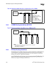
Note: A single clock output from CKBF is used to drive DCLKWR at the 82443GX. The single clock net
should be “T”d as close as possible to the 82443GX. An additional capacitive load of 20pF is also
required. The capacitor should also be located as close to the 82443GX as possible.
The 82443GX does not have an internal connection for pin AB22. Existing designs connected
DCLKWR & AB22 nets on the motherboard. Since the 82443GX does not have an internal
connection for pin AB22, it will cause a slightly reduced load capacitance on the net. To avoid
additional clock skew on existing designs, a discrete capacitor larger than the 20pF capacitor
recommended may be required.
Net Trace length min max Substrate
Clock chip - PCI connector H + 4.8” 1.0” 12.5” 2.5”
Clock chip - PIIX4E H + 7.3” 1.0” 15.0” NA
Clock chip -440GX H + 7.3” 1.0” 15.0” NA
Net Trace Length Min Max Cap
440GX - CKBF (DLKO) NA 1.0” 10.0” NA
CKBF - DIMM (SDRAM Clocks) A 1.0” 3.0” NA
CKBF - 82443GX (DCLKWR) A+2.5” 3.5”5.5” 20pF


