Intel
®
440GX AGPset Design Guide
3-2
Design Checklist
3.3 Intel
®
Pentium
®
II Processor Checklist
3.3.1 Intel
®
Pentium
®
II
Processor
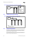
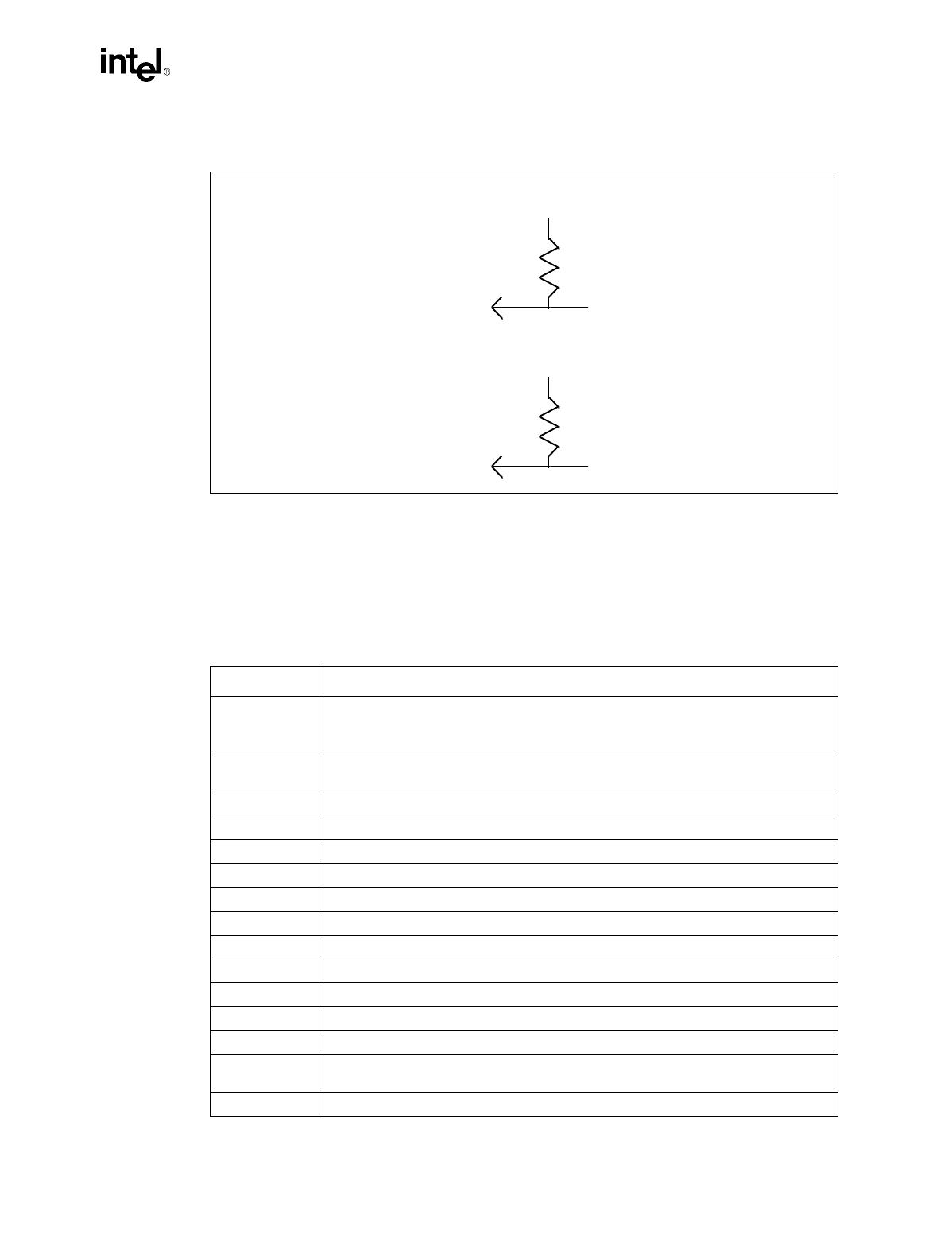
Figure 3-1. Pull-up Resistor Example
Table 3-1. Slot Connectivity (Sheet 1 of 3)
Processor Pin Pin Connection
100/66#
UP:
Connected to CK100. 10K ohm series resistor to MAB#12. 200 ohm pull-up to 3.3V at
CK100.
DP
: connect between CPUs (Logic may be provided to detect a frequency match).
A[35:32]#,
A[31:3]
Leave as NC, connect A[31:3]# to 82443GX.
A20M# 150 ohm - 330 ohm pull-up to 2.5V.
ADS#
UP:
Connect to 82443GX;
DP
: Connect CPUs and 82443GX
AERR# Leave as NC.
AP[1:0]# Leave as NC.
BCLK Connect to CK100. 22 ohm series resistor.
BERR# Leave as NC.
BINIT# Leave as NC.
BNR#
UP:
Connect to 82443GX;
DP
: Connect CPUs and 82443GX
BP[3:2]# Leave as NC.
BPM[1:0] Leave as NC.
BPRI#
UP:
Connect to 82443GX;
DP
: Connect CPUs and 82443GX.
BREQ[1:0]#
UP
: Connect BREQ0# to 82443GX. Leave BREQ1# as NC.
DP
: Connect BREQ0# of
each CPU to BREQ1# of the other. Connect one of these to 82443GX.
D[63:0]#
UP:
Connect to 82443GX;
DP
: Connect CPUs and 82443GX.
V
IH
MIN
Vcc
PU
MIN
R
MAX
V
IL
MAX
Vcc
PU
MAX
R
MIN
I
Leaka
g
e
MAX
I
OL
MAX


