Intel
®
440GX AGPset Design Guide
3-10
Design Checklist
3.5 82443GX Host Bridge
3.5.1 82443GX Interface
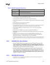
Table 3-4. 82443GX Connectivity (Sheet 1 of 3)
SIGNAL CONNECTION
AD#[31:0] Connected to PCI bus.
ADS# Connected to CPUs.
AGPREF Connected to be 0.4 of VCC
3.3
. Can be performed by a voltage divider.
BNR# Connected to CPUs
.
BPRI# Connected to CPUs.
BREQ0# Connected to CPUs.
GXPWROK Connected to PIIX4E PWROK pin.
C/BE[3:0]# Connected to PCI bus.
FENA
4DIMM Design
: Connected to FET-switches as an enable pin.
GCKE
GCKE needs to be disabled for re
g
ister DIMMS
.
GCKE is a NC unless connected to SN74ALVCH16374 16-bit D flip-flop. See
reference schematics for details.
CLKRUN#
If not connected to the PIIX4E, pull down through a 100 ohm resistor at both
82443GX and PIIX4E.
CPURST# Connected to CPUs and ITP (240 ohm series resistor).
CRESET# 10K ohm pull-up to 3.3V. Controls the mux for the CPU strapping signals.
CSA[5:0]# Connect to DIMMs; two to each
CSA[7:6]# Connect CSA[7:6]# to DIMM 3.
CSB[5:0]# Connect to DIMMs; two to each
CSB[7:6]# Connect CSB[7:6]# to DIMM 3
DBSY#, DRDY# Connected to CPUs.
DCLKO
Connected to CKBF. 22 ohm series resistor placed next to 443GX and 47 ohm series
resistor placed next to CKBF.
DCLKWR,
Pin AB22 (NC)
Driven by single clock from CKBF. See Clock section
DEFER# Connected to CPUs.
DEVSEL# 2.7K ohm pull-up to 5V. Connected to PCI bus.
DQMA[7:0] Connected to all DIMMs.
DQMB5, DQMB1 4 DIMM: Connected to DIMM2 and DIMM3.
FRAME# 2.7K ohm pull-up to 5V. Connected to PCI bus.
GAD[31:0], GC/
BE[3:0]#
Connected to AGP connector.
GCLKIN Connected to GCLKOUT through 22 ohm resistor.
GCLKOUT Connected to AGP connector through 22 ohm series resistor.


