


Chapter 4—Maintenance
Model 330, 340SC, and 370SC Service Manual
4-11
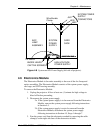
Example:
If the center brightness is 20 foot-candles, the ideal edge
brightness should be 10 foot-candles.
CAUTION!
Do not allow roll-off to be greater than 4:1
or damage to the Cold Mirror could result. Refer to Section 3.11
information on how to check roll-off.
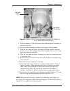
3.
In some cases it may also be necessary to adjust the vertical and horizontal
orientation of the collimating lens to achieve maximum brightness.
CAUTION!
This adjustment can be sensitive
and should not be attempted unless all other measures have
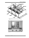
been tried first. To do this, loosen the three (3) mounting
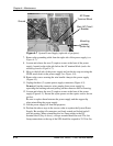
screws on the rear of the condenser lens mount (
see
Figure
4-6
) and move the collimating lens to orient the hot-spot
(brightest area) to the center of the screen.
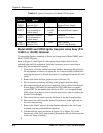
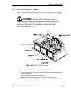
4.5 System Power Supply
The System Power Supply is located immediately forward of the electronics card
cage.
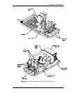
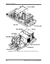
To remove the system power supply (see Figure 4-4 and Figure 4-5 and Figure
4-7):
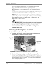
1.
Unplug the projector. Allow at least one (1) minute for high voltage to
bleed off before proceeding.
2.
Remove the rear projector cover (Section 4.2).
3.
Remove the two (2) screws from the Plexiglas cover over the terminal
block (top of SPS, forward-Figure 4-1) and remove cover.
4.
Label and remove the arc lamp ignitor cables, J503 and J504, and the
shield ground wire from the DC terminal block.
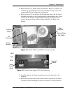
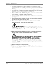
5.
Remove the Plexiglas cover from the AC input terminal block located on
the right side of the power supply (see Figure 4-7).
6.
Ensure power is disconnected then remove the three (3) AC input wires
from the AC terminal block:
Green (or Yellow/Green) left terminal (Ground).
White (or Blue) middle terminal (Neutral).
Black (or Brown) right terminal (Hot).
NOTE:
Colors may be different, depending on country of use.