


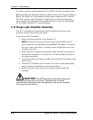

Chapter 4—Maintenance
4-18
Model 330. 340SC, 370SC Service Manual
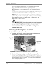
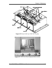
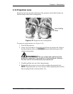
Model 340SC and 370SC CRT Removal
To remove a Model 340SC and 370SC CRT (see Figure 4-10):
1.
Unplug the projector. Wait at least one (1) minute before proceeding for
the high voltage to bleed off.
2.
Remove the electronics module (Section 4.6).
NOTE:
Removal and replacement of a CRT may be more easily
accomplished with the System Power Supply removed from the electronics
module. This is not absolutely necessary. It is at the technician’s discretion
to remove it or not (refer to Section 4.5).
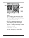
3.
After removing the System Power Supply, remove the System Power
Supply mounting plate that covers the top front area of the CRT Assembly.
4.
Run the CRT all the way forward using the Z axis focus rods at the rear of
the CRT assembly. This allows more room to remove the CRT socket.
5.
Remove the video amplifier board from the CRT Assembly (refer to
Section 4.8).
6.
Inside the CRT housing, remove the cable clamp(s) from the CRT anode
cable.
7.
Inside the CRT housing on the left side, disconnect the CRT anode cable
from the bulkhead connector. Ensure the entire anode cable is free. Loosen
the yoke clamp and ensure the yoke is loose on the CRT neck.
8.
Remove three (3) mounting screws at the face of the CRT. Gently remove
the CRT by sliding it forward out of the yoke and CRT housing.
9.
Replace the CRT in the reverse order.
10.
Perform a CRT Mechanical Focus adjustment and yoke alignment after
replacing the CRT (refer to Section 3.7 and 3.2).
Notes on replacing a Model 340SC and 370SC CRT:
Orient the CRT high voltage cable connector downward.
Remove the plastic coating from the tube screen only after the
CRT has been installed.
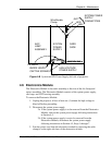
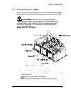
4.8 Video Amplifier Board (VAB)
The video amplifier boards are located inside the CRT housing. They are mounted
on and fully supported by the CRT neck. There is one (1) video amplifier board on
each CRT.
To remove a VAB (see Figure 4-9 or Figure 4-10):
1.
Unplug the projector. Wait at least a minute before proceeding for the high
voltage to bleed off.
2.
Remove the rear projector cover (Section 4.2).