


Chapter 2—Functional Descriptions
2-14 Model 330, 340SC, and 370SC Service Manual
As with the other indicators on that LED bar, the LED is in series with current
limiting resistor, so a lit LED indicates only the presence of a voltage, not
necessarily the correct voltage.
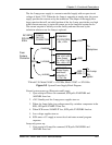
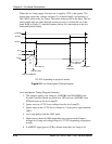
The control grid, G1, voltage is regulated to -81V during normal operation.
During blanking, G1 is pulled to -111V. When the CRTs are disabled for
protection, G1 is pulled to its maximum negative level of -200V, which can be
measured, at the control connector, pin 6.
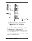
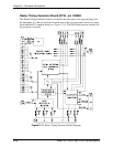
2.5 Card Cage
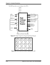
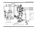
The Card Cage provides support and protection for five (5) circuit boards, the
Phase Locked Loop and the optional Decoder Board in the HJT Model 330,
340SC and 370SC projectors. The five-(5) circuit boards are, from rear to front,
the VPB, RTG, SCB, VDB, and HDB. Each circuit board has it's own keyed slot.
A circuit board cannot easily be plugged into the wrong slot since the connectors
will not match up.
Horizontal Deflection Board (HDB) P/N 102523
Vertical Deflection Board (VDB) P/N 102521
System Controller Board (SCB) P/N 104668
Raster Timing Generator
and Phase Locked Loop
(RTG)
(PLL)
P/N 100568
Video Processor Board
and optional Decoder Board
(VPB) P/N 104672
Figure 2-9
Electronics Card Cage
Four (4) fans on the right side of the card cage cool the circuit cards in the card
cage. These fans are energized by the +24V standby power from the SPS. They
start when either the Arc Lamp or the electronics are powered up and run for
approximately five (5) minutes after the projector is shut down.
The five-(5) cards in the card cage are held into position by both the friction of the
connectors and by a circuit board retaining bar. The circuit board retaining bar
should always be installed during projector operation.
A lightweight top cover is included with the card cage. Eight (8) screws secure the
cover. The cover provides for direction of air flow and for physical protection of
the circuit cards contained in the card cage. The cover should always be installed
when the projector is in operation to ensure adequate cooling of the circuit cards
and to prevent foreign materials from falling into the electronics.