


Chapter 2—Functional Description
Model 330, 340SC and 370SC Service Manual 2-23
I
T Blank
Commanded position of top blanking.
I
B Blank
Commanded position of bottom blanking.
I
/STBP
Command for DC restore timing on either
leading or trailing edge of sync pulse.
I
DC Restore Delay
Commanded timing of DC restore after
reference edge of sync pulse.
I
Internal Sync Forced
Command to force internal sync select.
I
Correction Start Delay
Commanded H phase of correction map.
I
Pincushion Start Delay
Commanded H phase of pincushion, keystone,
and linearity correction.
I
2H Sync Enable
Command determines path of H sync signal.
I
Shifted Sync Enable
Command determines path of H sync signal.
O
/External Sync Detect
Is an external sync available.
O
HCount
Count of H lines per frame.
O
/Phase Lock
Indication of PLL lock.
O
Phase Count
Indication of phase difference between
HSYNC and HFlyback.
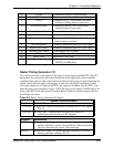
Raster Timing Generator I/O
This section provides a description of the inputs to and outputs from the RTG. The I/O
description are arranged by the source/destination of the signal and so the assemblies
communicated with are used as the primary heading of each group of signals and then are
further subdivided into inputs and outputs. In each case, the signal's direction is noted,
with input referring to an input to the RTG, and output to an output from the RTG. (e.g.:
under System Controller Board “Input”; SYSCLK refers to the signal SYSCLK that is an
input to the RTG from the System Controller Board). When test points are provided for
the I/O they are noted.
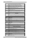
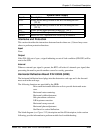
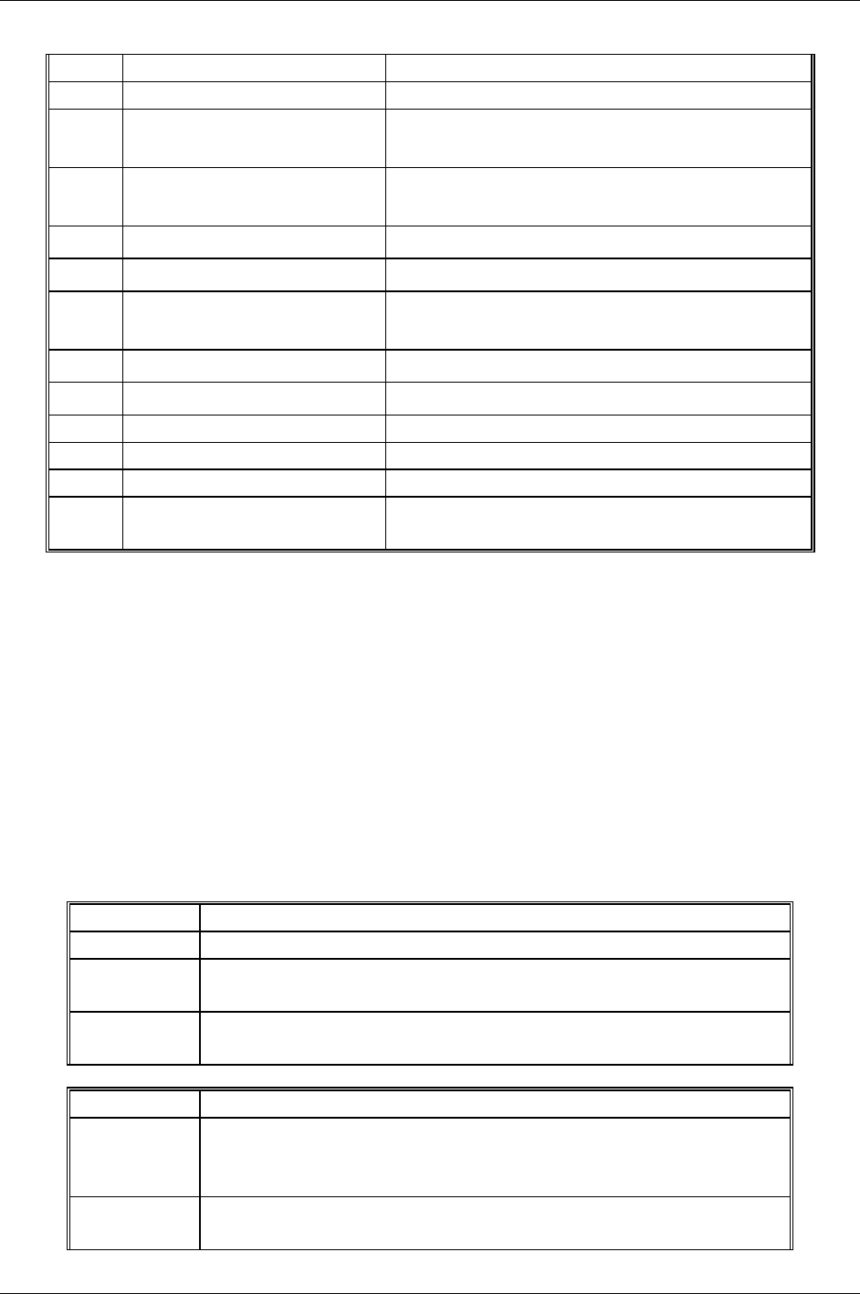
Table 2-5
Raster Timing Generator I/O Signals
System Controller Board
Inputs
Description
SYSCLK
4 MHz clock signal for derivation of internal HDTV sync signal.
(TP 13)
IICCLK
IIC clock line. Unidirectional clock line for control of
synchronous data transfer over IIC data bus.
Outputs
Description
/IICINT
IIC interrupt line. Signal line for slave boards to inform the SCB
(master) that there is data to be transferred. Master then polls
slaves to determine the source of the interrupt.
/Hx224
Square wave signal 224 X the horizontal frequency for overlay
address generator clocking. (TP 23)